Eureka AIR delivers breakthrough ideas for toughest innovation challenges, trusted by R&D personnel around the world.

Ship bilge keel mounting bed-jig template and mounting method thereof

An installation method and bilge keel technology, which is applied in the field of auxiliary tooling for the installation of ship bilge keels, can solve the problems of prolonging construction time, increasing procedures, and not adapting to the mode, etc., to achieve convenient and accurate positioning and installation, improve positioning accuracy, and improve work efficiency Effect

Inactive Publication Date: 2019-04-02
WUHU SHIPYARD CO LTD
View PDF6 Cites 2 Cited by
  • Summary
  • Abstract
  • Description
  • Claims
  • Application Information

AI Technical Summary

Problems solved by technology

When the outer bottom plate is constructed normally or the outer plate is side-built on the base of the tire frame, the bilge keel is always under the outer plate, and it cannot be hoisted in place by lifting and driving, and the scale of the bilge keel of large ships is very large. , the weight can be close to 0.5 tons, and it cannot be assembled safely by the construction personnel with bare hands. Therefore, after the segmental assembly and welding is completed, the segmental bodiless and turn over and set aside before installing the bilge keel, which virtually increases the segmental bodiless Turn over and segmental secondary assembly welding, this process arrangement hinders the number and speed of the segmented manufacturing workshop output, and does not adapt to the modern shipbuilding mode
Therefore, the bilge keel installation process in the prior art increases the workload of welding, cutting, repairing, and polishing of the lifting ring, and the section also has one more turn over, section shelving, and secondary assembly construction by construction personnel, which virtually increases The process is shortened, the construction time is prolonged, and the turning operation also increases the risk of operation

Method used


Image

  • Ship bilge keel mounting bed-jig template and mounting method thereof
  • Ship bilge keel mounting bed-jig template and mounting method thereof
  • Ship bilge keel mounting bed-jig template and mounting method thereof

Examples


Embodiment Construction

[0023] Below with reference to the accompanying drawings, through the description of the embodiments, the specific embodiments of the present invention, such as the shape, structure, mutual position and connection relationship between the various parts, the role and working principle of the various parts, etc., will be further described. Detailed instructions:

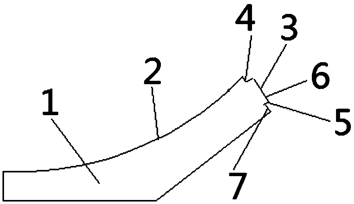
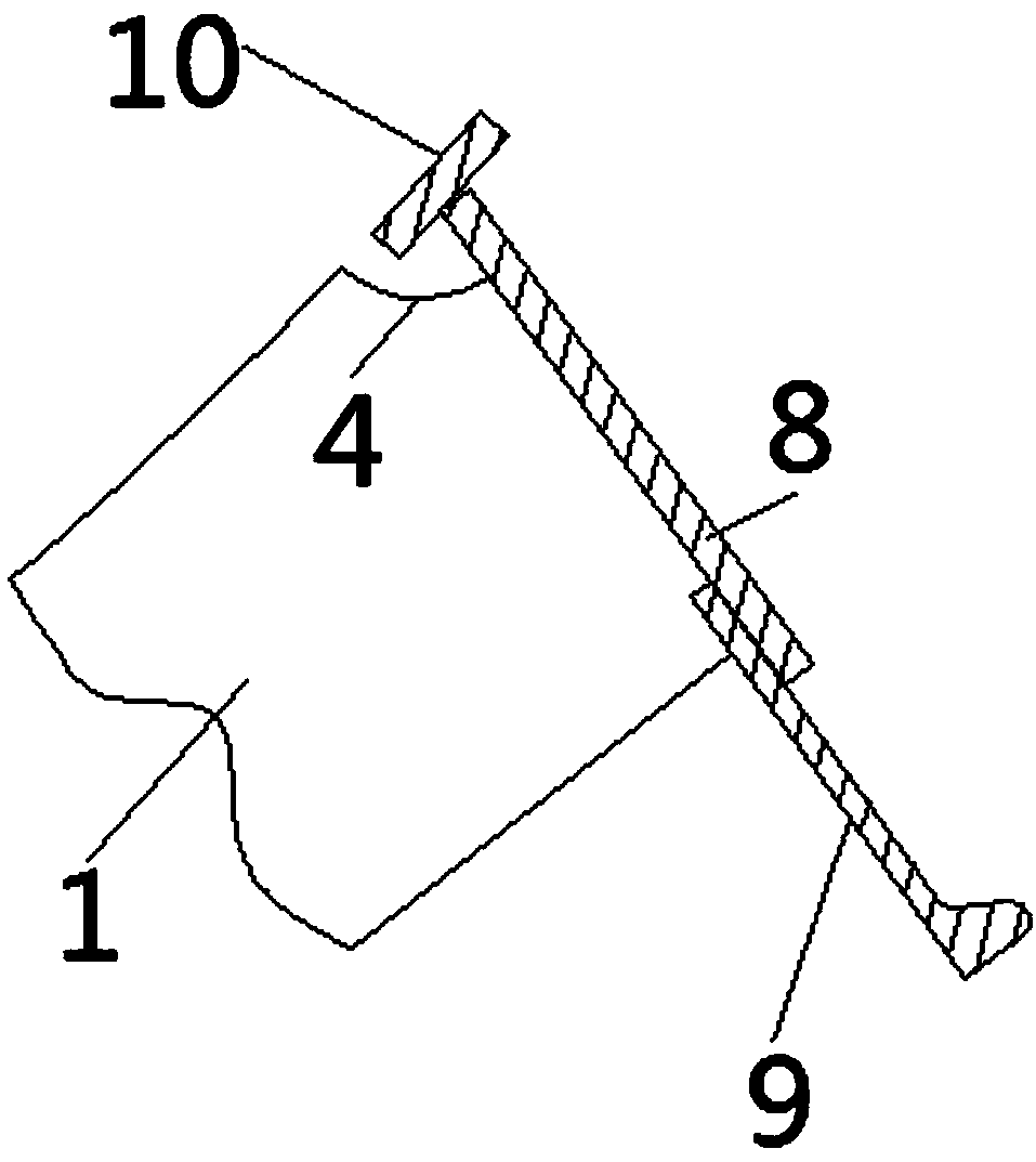
[0024] as attached figure 1 - attached Figure 4 As shown, the present invention is a ship bilge keel installation tire frame template, the ship bilge keel installation tire frame template includes a template plate 1, one end of the template plate 1 is a positioning arc portion 2, and the template plate 1 side is the bilge keel positioning part 3, the bilge keel positioning part 3 and the positioning arc part 2 are provided with a recessed part 4, and the bilge keel positioning part 3 is also provided with a step part 5, and the step part 5 connects the bilge keel positioning part 3 Divided into the first positioning...


PUM


Abstract

The invention provides a ship bilge keel mounting bed-jig template applied to the technical field of ship bilge keel mounting auxiliary tools. The invention further relates to a ship bilge keel mounting method. One end of a template piece (1) of the ship bilge keel mounting bed-jig template is a locating arc part (2); one side of the template piece (1) is a bilge keel locating part (3); a concavepart (4) is arranged at the combined part of the bilge keel locating part (3) and the locating arc part (2); a step part (5) is also arranged on the bilge keel locating part (3); and the step part (5)divides the bilge keel locating part (3) into a first locating surface (6) and a second locating surface (7). According to the ship bilge keel mounting bed-jig template and the ship bilge keel mounting method, the structure is simple, the ship bilge keel and a ship-hull plate can be conveniently and accurately located and mounted, and it is important that the workload of the ship bilge keel mounting process is effectively reduced by changing the mounting time section of the ship bilge keel.

Description

technical field [0001] The invention belongs to the technical field of auxiliary tooling for installation of ship bilge keels, and more specifically relates to a ship bilge keel installation tire frame template, and the invention also relates to a ship bilge keel installation tire frame template using a ship bilge keel installation tire frame template for installation of ship bilge keel installation method. Background technique [0002] Ships roll under the influence of wind and waves during navigation, and rolling is harmful to the stability of the ship and the comfort of the people on board. In order to reduce the rolling amplitude and rolling frequency of the ship and improve the stability and comfort of the ship, a longitudinal bilge keel is usually arranged on the outer side of the bilge outer plate (hull outer plate) in the middle of the ship. Compared with the hull structure, the bilge keel is much simpler in terms of quantity and structural complexity, so the method...

Claims


Application Information

Patent Timeline
Patent Type & Authority Applications(China)
IPC IPC(8): B63C5/02B63B9/00B63B39/06
CPCB63B39/06B63B71/00B63B2039/067B63C5/02B63C2005/025
Inventor 张锦秀李仁兰敏超杨小龙戴舞真
Owner WUHU SHIPYARD CO LTD
Why Eureka
Eureka Blog
Learn More