Dual-vacuum chamber and dual-frequency phase measurement air refractivity interferometer

A double vacuum chamber, refractive index technology, applied in the field of laser

Inactive Publication Date: 2002-12-04
TSINGHUA UNIV
View PDF9 Cites 6 Cited by
  • Summary
  • Abstract
  • Description
  • Claims
  • Application Information

AI Technical Summary

Problems solved by technology

The advantages of stable measurement results

Method used


Image

  • Dual-vacuum chamber and dual-frequency phase measurement air refractivity interferometer
  • Dual-vacuum chamber and dual-frequency phase measurement air refractivity interferometer
  • Dual-vacuum chamber and dual-frequency phase measurement air refractivity interferometer

Examples


Embodiment Construction

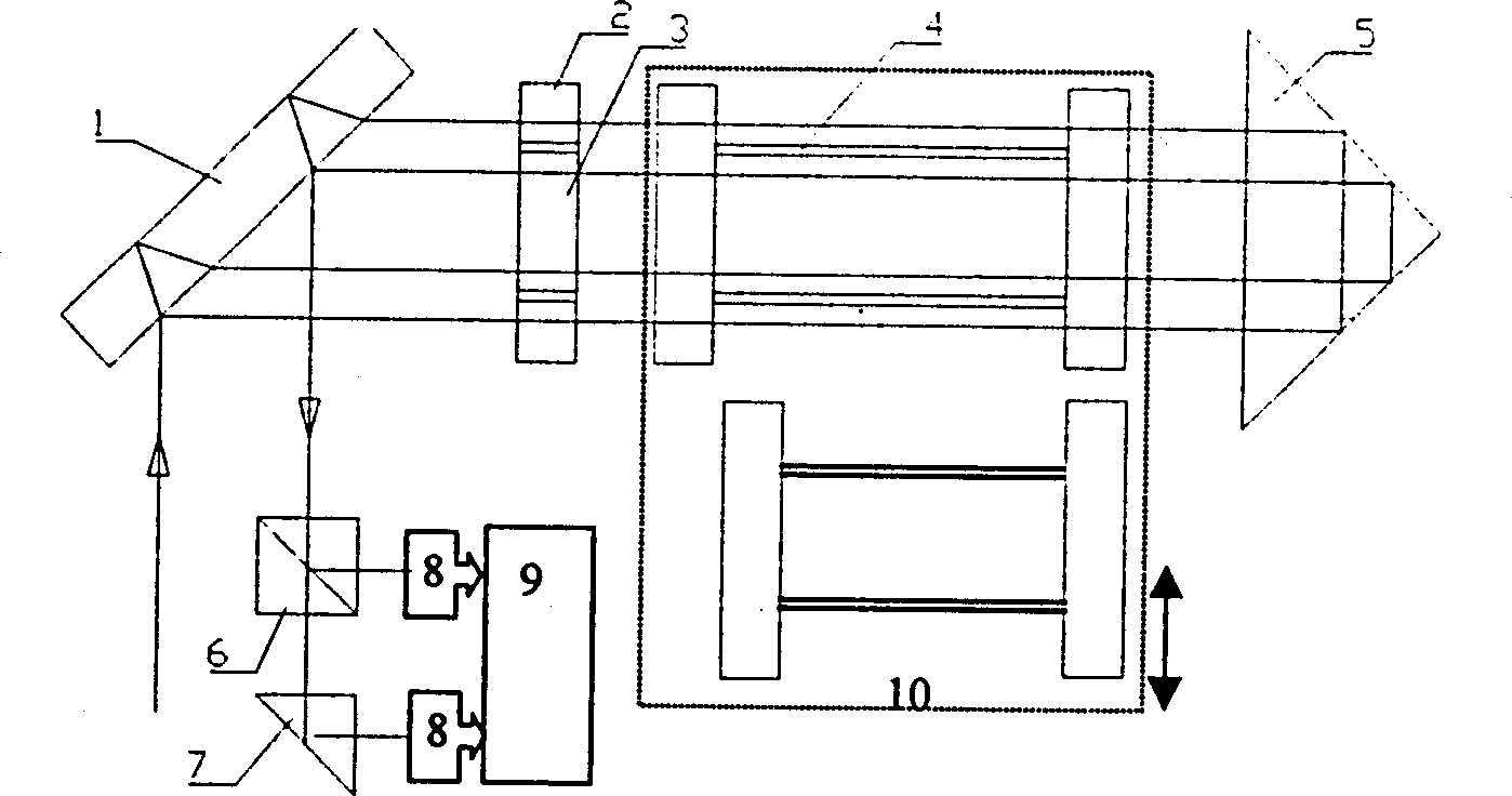
[0026] An embodiment of a dual-vacuum chamber dual-frequency phase-measuring air refractive index interferometer of the present invention image 3As shown, it mainly includes: a transverse Zeeman laser emitting orthogonal linearly polarized light, a beam splitter 1 that splits the light emitted by the laser into two beams and reflects it in a vertical direction, and is perpendicular to the optical axis of the light reflected by the beam splitter The set compensation ring 2 and the 1 / 4 wave plate 3 placed therein, the rectangular tetrahedral reflector 5, and two parallel to the optical axis arranged between the said 1 / 4 wave plate and the rectangular tetrahedral reflector Vacuum chambers 41, 42 of different lengths, said two vacuum chambers are fixed on a drag stage 10 driven by an ultrasonic linear motor to send two vacuum tubes into the interference optical path, and also include a device for receiving reflected light from the beam splitter Polarization beam splitter 6 and to...


PUM


Abstract

The present invention comprises light-splitting plate capable of splitting up the light transmitted by transverse Zeeman laser into two beams and reflecting them, compensating ring set perpendicular to optical axis and 1/4 wave sheet placed in the compensating ring, two length-different vacuum chambers placed between 1/4 wave sheet and right-angle tetrahedral reflector and parallel to optical axis, polarizing reflecting prism and fully-reflecting prism for receiving reflected returning light, two photo-electric delectors and one phaser and data processor connected with phaser. Said invention can raise measuing accuracy and resolution, and can be combined into portable instrument, and possesses self-adaptivity for environmental vibration and drift of optical beam.

Description

technical field [0001] The invention belongs to the field of laser technology, in particular to the structural design of an air refractive index interferometer. Background technique [0002] In 1965, Bengt Edlen used a large number of experimental results to formulate an empirical formula. The refractive index of air is related to atmospheric pressure, temperature, humidity, and carbon dioxide content, which is the famous Edlen formula. Due to the difference between the current atmospheric conditions and that at that time, especially the change of carbon dioxide content and the change of air composition caused by the volatilization of solvents in the laboratory, the calculated value of the formula deviates from the actual refractive index of air. After several revisions, it is still unable to adapt to the changing experimental environment. [0003] In 1979, Tsinghua University successfully researched the dual-frequency (air pumping) refractive index interferometer and estab...

Claims


Application Information

Patent Timeline
Patent Type & Authority Patents(China)
IPC IPC(8): G01N21/45
Inventor 殷纯永王泽民赵淳生武三峨郭松灵
Owner TSINGHUA UNIV
Why Eureka
Try Eureka