Continuous roll-to-roll vacuum coating machine

A vacuum coating machine, roll-to-roll technology, applied in vacuum evaporation coating, sputtering coating, ion implantation coating, etc., can solve problems such as slow production efficiency, improve coating efficiency, save production costs, and solve production problems The effect of inefficiency

Pending Publication Date: 2019-04-02
浙江德佑新材料科技有限公司
View PDF0 Cites 2 Cited by
  • Summary
  • Abstract
  • Description
  • Claims
  • Application Information

AI Technical Summary

Problems solved by technology

The traditional photoelectric thin film coating process mostly uses a single method, such as magnetron sputtering,

Method used


Image

  • Continuous roll-to-roll vacuum coating machine

Examples


Embodiment Construction

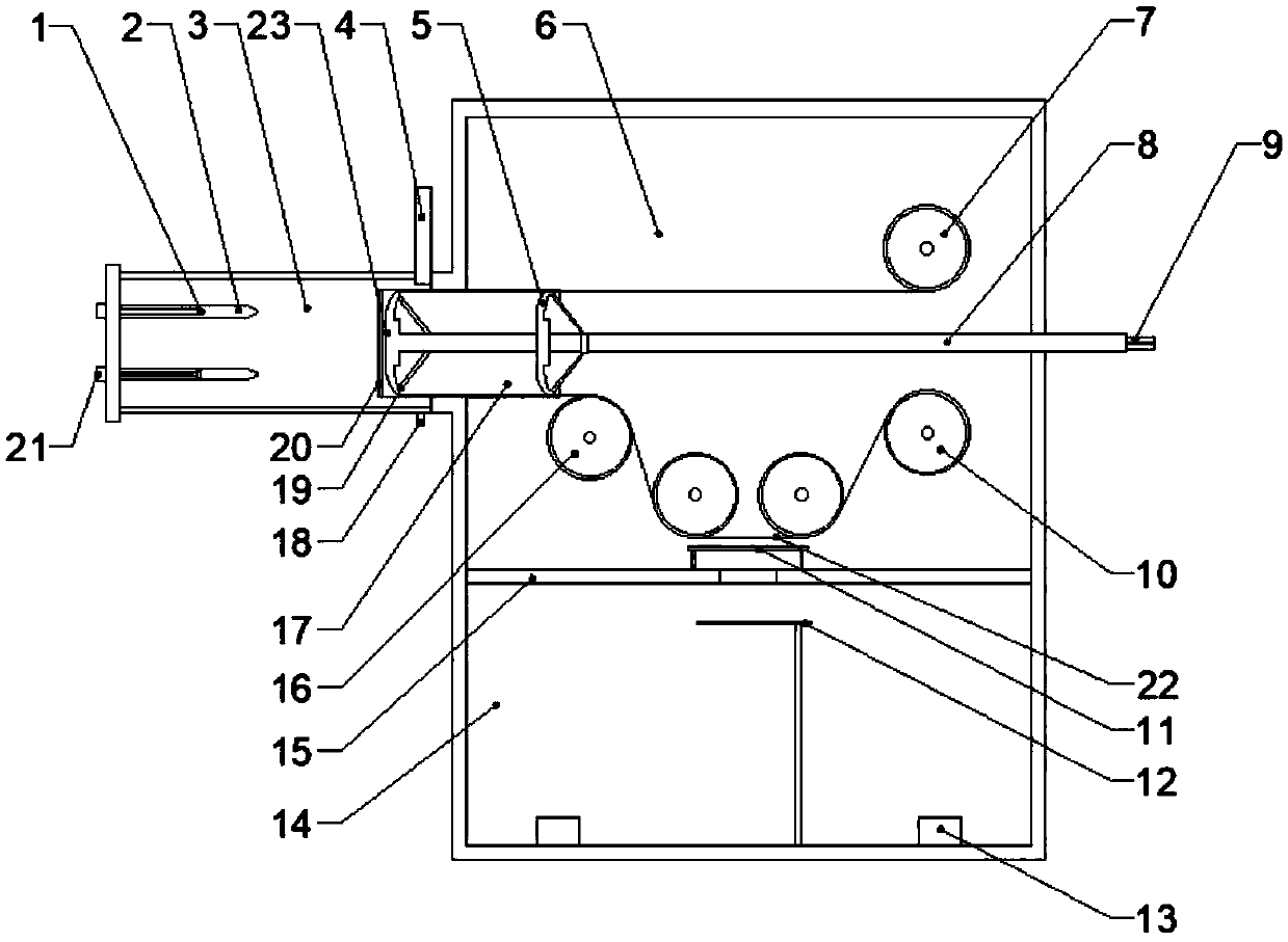
[0023] In order to better explain the present invention and facilitate understanding, the present invention will be described in detail below through specific embodiments in conjunction with the accompanying drawings.

[0024] The invention provides a continuous roll-to-roll coating machine, such as figure 1 As shown in the schematic diagram of the device structure of the present invention, the vacuum coating machine includes a first coating chamber 14, a second coating chamber 3 and a delivery chamber 6, and the first coating chamber 14 includes an evaporation boat 13 and an evaporation baffle 12 , the second coating chamber 3 contains the cathode tube 2, the second shade net 20 and the electromagnetic gate valve 4, and the conveying chamber 6 contains a pushing device, a winding device, and the first shade net 11, and the pushing device includes a first The pushing device 5 , the second pushing device 19 , the pushing rod 8 , the cylindrical steel web 17 , and the winding de...


PUM


Abstract

The invention relates to the technical field of vacuum coating, in particular to a continuous roll-to-roll vacuum coating machine. The vacuum coating machine comprises a first coating chamber, a second coating chamber and a conveying chamber, wherein the first coating chamber internally comprises an evaporation boat and an evaporation baffle plate; the second coating chamber internally comprises acathodic electric arc evaporation source, a cathode pipe and a second overshadowing net; the conveying chamber internally comprises a pushing device, a coiling device and a first overshadowing net; the pushing device comprises a first pushing device, a second pushing device, a pushing rod and a cylindrical steel web plate; a partition plate is arranged between the first coating chamber and the conveying chamber; and the partition plate is connected with the conveying chamber in an airtight manner. The continuous roll-to-roll vacuum coating machine disclosed by the invention has the advantagesthat two processes of organic gas phase deposition and vacuum evaporation coating are combined, and because the coiling device is additionally arranged, the coating efficiency is greatly improved, and the problem that the production efficiency of flexible electro-optical films is insufficient is solved.

Description

technical field [0001] The invention relates to the technical field of vacuum coating, in particular to a continuous roll-to-roll vacuum coating machine. Background technique [0002] In recent years, the application of flexible substrate films has become more and more extensive. With the development of optoelectronic technology, the production efficiency and quality requirements of flexible optoelectronic films have gradually increased. The traditional photoelectric thin film coating process mostly uses a single method, such as magnetron sputtering, chemical vapor deposition, etc., and the production efficiency is slow, which is far from meeting the market demand. In terms of coating equipment, roll-to-roll coating equipment has gradually attracted people's attention because of its high production efficiency and excellent characteristics of being able to prepare flexible films. However, due to different machine requirements for paper coating and plastic film processes, for ...

Claims


Application Information

Patent Timeline
IPC IPC(8): C23C14/24C23C14/32C23C14/56
CPCC23C14/24C23C14/325C23C14/562C23C14/568
Inventor 李正平李成林
Owner 浙江德佑新材料科技有限公司
Why Eureka
Try Eureka