
Liquid external combustion engine

An external combustion engine technology, applied in the direction of rotary piston engine, machine/engine, rotary or swing piston engine, etc., can solve the problem of large size, achieve the effect of small device size, high thermal efficiency, and reduce system pressure

Active Publication Date: 2019-04-02
山东万物生机械技术有限公司
View PDF6 Cites 0 Cited by
  • Summary
  • Abstract
  • Description
  • Claims
  • Application Information

AI Technical Summary

Problems solved by technology

[0005] The invention provides a liquid external combustion engine, the purpose of which is that the current external combustion engine has a large volume and is suitable for a small carrier, and when driving a large power element, the gas medium is reversed due to compression improve the situation

Method used


Image

  • Liquid external combustion engine
  • Liquid external combustion engine

Examples


Embodiment Construction

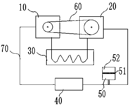
[0021] The embodiment of the present application provides a liquid external combustion engine, which mainly solves the problems of the current external combustion engine, such as insufficient thermal efficiency, large device volume so that its use is limited, and inability to effectively drive high-power workpieces. In the pump body, the heater heats the internal working medium. Due to the pressure difference between the two ends of the pump body and the different displacement of the two pump bodies, the working medium flows from the side with high pressure to the side with low pressure, thereby driving the output shaft to rotate. acting.

[0022] In order to better understand the above-mentioned technical solution, the technical solution of the present invention is described in detail below in conjunction with the accompanying drawings and specific embodiments:

[0023] Such as figure 1 As shown, the present application is a liquid external combustion engine, which mainly in...


PUM


Abstract

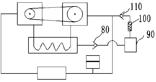
The invention relates to a liquid external combustion engine. The liquid external combustion engine mainly comprises a gear pump A, a connecting device, a gear pump B, a heater, a circulation pipeline, a condenser and a pressure reducing device, wherein an output shaft of the gear pump A is connected with one end of the connecting device; an output shaft of the gear pump B is connected to the other end of the connecting device; connecting openings at the two ends of the heater are correspondingly connected with an outlet of the gear pump B and an inlet of the gear pump A; the circulation pipeline is connected between the inlet of the gear pump A and an inlet of the gear pump B; and the condenser and the pressure reducing device are arranged on the circulation pipeline. The gear pump A andthe gear pump B need to meet the condition that P<1>W<1> is not equal to P<2>W<2>, wherein P<1> and P<2> are the displacement of the gear pump A and the gear pump B correspondingly, and W<1>and W<2>are the rotating speed of the gear pump A and the gear pump B correspondingly. The liquid external combustion engine further comprises a fluid supplementing system and an overflow loop. The liquid external combustion engine utilizes the pressure difference inside the two gear pumps to form internal circulation for power output, the overall size is more compact, and the thermal efficiency is higher.

Description

technical field [0001] The invention belongs to the field of engines, and in particular relates to a liquid external combustion engine. Background technique [0002] An engine is a machine that can convert other forms of energy into mechanical energy, including internal combustion engines, external combustion engines, electric motors, etc. Internal combustion engines usually convert chemical energy into mechanical energy, including gasoline engines, diesel engines, and jet engines. The external combustion engine is the combustion of fuel outside the engine, and the engine converts the heat energy generated by this combustion into kinetic energy, such as a Stirling engine and a steam engine. Compared with external combustion engines, internal combustion engines have the advantages of high thermal efficiency and small size, but they also have disadvantages such as complex structure, high precision, high cost, and high requirements for operation and maintenance skills. [000...

Claims


Application Information

Patent Timeline
Patent Type & Authority Applications(China)
IPC IPC(8): F03C2/08
CPCF03C2/08
Inventor 姚长水
Owner 山东万物生机械技术有限公司
Learn More