Eureka AIR delivers breakthrough ideas for toughest innovation challenges, trusted by R&D personnel around the world.

Passive laser gyroscope based on ultra-stable laser

A laser gyro and passive technology, applied in the field of laser gyroscopes, can solve the problems of poor stability and insufficient detection resolution, and achieve the effects of improving detection sensitivity, improving the signal-to-noise ratio of interference signals, and improving detection resolution

Active Publication Date: 2019-04-02
HUAZHONG UNIV OF SCI & TECH
View PDF10 Cites 11 Cited by
  • Summary
  • Abstract
  • Description
  • Claims
  • Application Information

AI Technical Summary

Problems solved by technology

[0005] In view of the above defects or improvement needs of the prior art, the present invention provides a passive laser gyroscope based on ultra-stable lasers, which aims to solve the problem of detection caused by injected laser noise and poor stability of the gyroscope in the existing passive laser gyroscope. The resolution is not high enough. By improving the stability of the passive laser gyroscope injection laser source and the stability of the scale factor, the laser line width is much smaller than the line width of the ring cavity, and the signal-to-noise ratio of the laser gyroscope interference signal is improved. At the same time, the laser gyroscope Rotation detection sensitivity of the instrument and long-running integration time, resulting in improved rotation detection resolution

Method used


Image

  • Passive laser gyroscope based on ultra-stable laser
  • Passive laser gyroscope based on ultra-stable laser
  • Passive laser gyroscope based on ultra-stable laser

Examples


Embodiment Construction

[0022] In order to make the object, technical solution and advantages of the present invention clearer, the present invention will be further described in detail below in conjunction with the accompanying drawings and embodiments. It should be understood that the specific embodiments described here are only used to explain the present invention, not to limit the present invention. In addition, the technical features involved in the various embodiments of the present invention described below can be combined with each other as long as they do not constitute a conflict with each other.

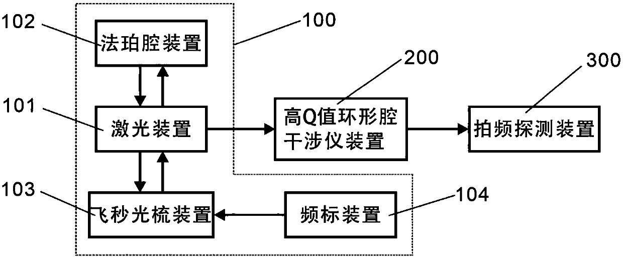
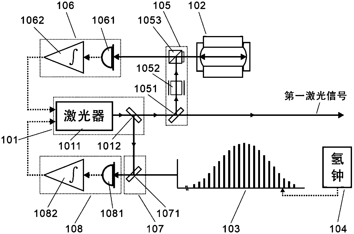
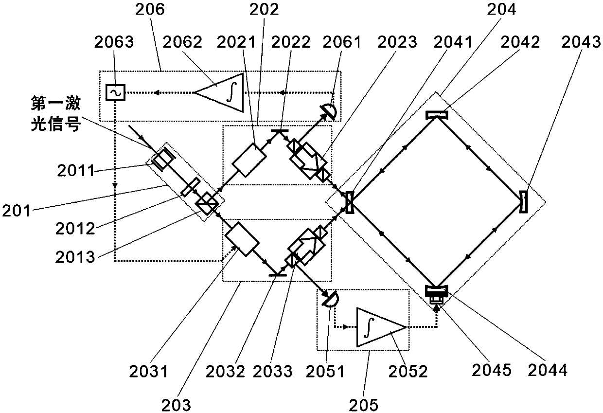
[0023] The invention provides a passive laser gyroscope based on an ultra-stable laser, figure 1 It is an overall structure diagram of the present invention, which mainly consists of an ultra-stable laser light source device 100 , a high-Q annular cavity interferometer device 200 and a beat frequency detection device 300 . The ultra-stable laser light source device 100 includes: a laser device ...


PUM


Abstract

The invention discloses a passive laser gyroscope based on an ultra-stable laser. The passive laser gyroscope comprises an ultra-stable laser source device, a high Q-value annular cavity interferometer device, and a beat frequency detecting device. An ultra-stable laser source with both short and long stability is obtained by locking the frequency of lasers output form a laser to an ultra-stable Fabry-Perot resonance peak and simultaneously locking to a femtosecond optical comb linked to an atomic frequency standard. The circumference of an annular cavity is locked to the frequency of the ultra-stable laser source injected in the counterclockwise direction. The frequency of the laser injected in the clockwise direction is locked to the same resonance peak of the cavity. The beat frequencydetecting device detects the beat frequencies of the overflow light in two directions in the cavity to obtain a Sagnac signal, and angular spin velocity is determined by the signal. According to the passive laser gyroscope based on the ultra-stable laser, the interference signal-to-noise ratio of the laser gyroscope is improved, and the stability of the scale factor of the gyroscope is improved byusing an ultra-stable laser as the injection light source of the passive laser gyroscope, so that the stability of the whole gyroscope system is improved, the integration average time is prolonged, and a better rotation measurement resolution can be obtained.

Description

technical field [0001] The invention belongs to the field of laser gyroscopes, and more specifically relates to a passive laser gyroscope based on ultra-stable laser technology. Background technique [0002] Laser gyroscopes are used in inertial navigation, geophysics, fundamental physics and other fields due to their excellent rotational rate measurement performance. In the past 40 years, laser gyroscopes have become the most important instruments in the fields of inertial navigation and precision rotation measurement, and are favored by researchers in scientific and industrial circles due to their high resolution, good stability, and wide dynamic range. The laser gyroscope is based on the Sagnac effect, which was proposed by the French scientist Sagnac in 1913. In a ring cavity, if the system rotates on the plane of light propagation, the actual distance between the light propagating clockwise and the light propagating counterclockwise The optical paths are not equal. If ...

Claims


Application Information

Patent Timeline
IPC IPC(8): G01C19/66
CPCG01C19/661
Inventor 张洁柳奎张风雷陆泽晃
Owner HUAZHONG UNIV OF SCI & TECH
Why Eureka
Eureka Blog
Learn More