A capacitive humidity sensor interface circuit
A technology of humidity sensor and interface circuit, applied in the field of sensors, can solve the problem of no signal output, etc., to achieve the effect of detection
- Summary
- Abstract
- Description
- Claims
- Application Information
AI Technical Summary
Problems solved by technology
Method used
Image

Examples
Embodiment 1
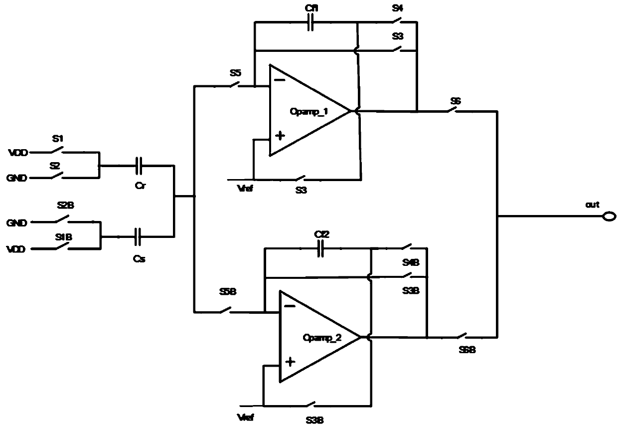
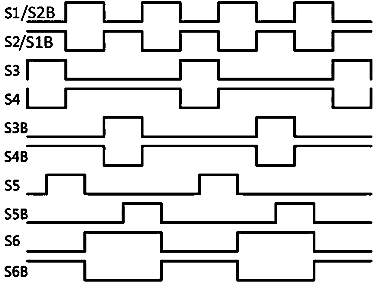
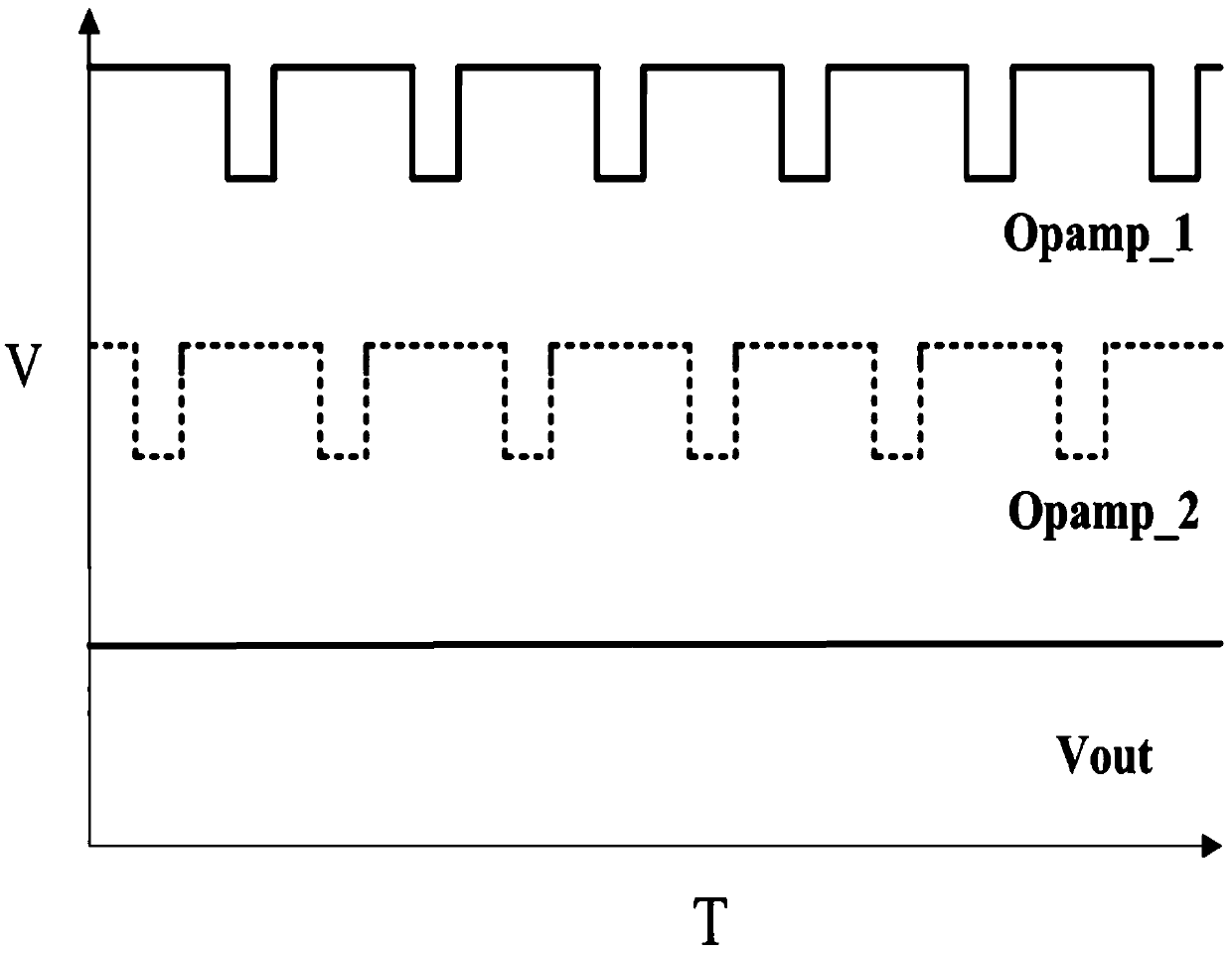
[0028] The present invention proposes a capacitive humidity sensor interface circuit, which adopts the alternate sampling method of double operational amplifiers, so that the circuit can continuously output amplified signals, such as figure 1As shown, the following setting method is specially adopted: including detection branch, reference branch, two-stage amplification branch, the detection branch and the reference branch are connected together and respectively connected to the input side of the two-stage amplification branch, and the two-stage amplification The output side of the branch is connected together and forms the output of the interface circuit, and a capacitive feedback branch connected to the input side and the output side is also provided on the two-stage amplification branch; the circuit works in a time-sharing manner through clock control, using The capacitive feedback form and the charge accumulation effect convert the change of capacitance into the change of v...
Embodiment 2
[0030] This embodiment is further optimized on the basis of the above embodiments, such as figure 1 As shown, further in order to better realize the present invention, the following arrangement is adopted in particular: the detection branch includes a humidity-sensitive capacitor Cs and a clock logic circuit, and a reference capacitor Cr and a clock logic circuit are also arranged on the reference branch; One end of the humidity sensitive capacitor Cs and one end of the reference capacitor Cr are all connected to the clock logic circuit, and the other end of the humidity sensitive capacitor Cs is connected to the other end of the reference capacitor Cr and is connected to the input side of the two-stage amplifying branch; The humidity-sensitive capacitor Cs changes its capacitance value by detecting changes in external humidity. The reference capacitor Cr adopts the same structure as the humidity-sensitive capacitor Cs, but its capacitance value does not change with humidity. ...
Embodiment 3
[0032] This embodiment is further optimized on the basis of any of the above embodiments, such as figure 1 As shown, further in order to better realize the present invention, the following setting method is adopted in particular: the clock logic circuit includes logic switch S1, logic switch S2, logic switch S1B, logic switch S2B, and logic switch S1 and logic switch S2 Commonly connected, logic switch S1B and logic switch S2B are commonly connected, and the common connection terminal of logic switch S1 and logic switch S2 is connected to reference capacitor Cr, and the common connection terminal of logic switch S1B and logic switch S2B is connected to humidity sensitive capacitor Cs.
PUM
 Abstract
Description
Claims
Application Information
 - R&D
- Intellectual Property
- Life Sciences
- Materials
- Tech Scout
- Unparalleled Data Quality
- Higher Quality Content
- 60% Fewer Hallucinations
Browse by: Latest US Patents, China's latest patents, Technical Efficacy Thesaurus, Application Domain, Technology Topic, Popular Technical Reports.
© 2025 PatSnap. All rights reserved.Legal|Privacy policy|Modern Slavery Act Transparency Statement|Sitemap|About US| Contact US: help@patsnap.com