
A power transmission cable

A power transmission and cable technology, applied in the field of power transmission cables and cables for power transmission, can solve the problems of inconvenient cable fixing and layout, low efficiency, easy rolling of circular structures, etc., to improve laying efficiency and wide application range. , the effect of easy connection

Active Publication Date: 2021-02-12
广东易初科技股份有限公司
View PDF10 Cites 0 Cited by
  • Summary
  • Abstract
  • Description
  • Claims
  • Application Information

AI Technical Summary

Problems solved by technology

[0002] At present, in the power transmission process, the cable is an essential carrier, and the power is transmitted through the cable. At present, most of the cables on the market are round, and the cable conductors are twisted from multiple wires, and then filled, shielded, protected, and produced. The workmanship is very perfect, but because the cables are circular, the distances between each position are the same, and it cannot be used in places with small spaces, such as the power transmission inside the power equipment and inside the machine, and the fixation and layout of the thick cables have problems. It is inconvenient to come, and the circular structure is easy to roll, which affects the layout of the cable, forms entanglement on the surrounding cables, and the cable conductor is wrapped layer by layer. When connecting, it is necessary to peel off the outer skin of the cable one by one, and then layer by layer from the inside to the outside. Connecting insulation is inefficient, time-consuming and labor-intensive. At the same time, when the diameter of the cable is too large, the radius of gyration required during the laying process also increases, and the demand for space increases. When the reel is wound, it also takes up a large space. , although there are also flat cables, but because the existing flat cables have an integrated structure and the multi-strand conductors are relatively fixed, they cannot be bent and rolled along the end surface, and the use method is single. It is necessary to avoid the conductor from being damaged when fixing

Method used


Image

  • A power transmission cable
  • A power transmission cable

Examples


Embodiment Construction

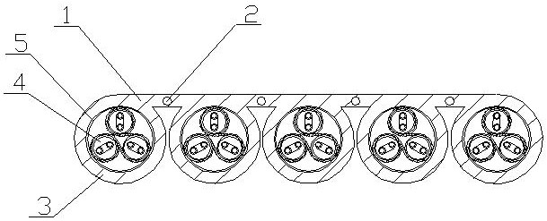
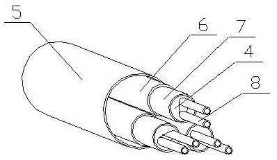
[0026] A power transmission cable of the present invention is realized in the following way: a power transmission cable of the present invention consists of a fixed base plate (1), load-bearing steel wire (2), outer protective sheath (3), wire (4), and non-woven fabric (5) , aluminum foil (6), wire insulation layer (7) and wire core (8), a plurality of outer protective sleeves (3) are equidistantly placed on the fixed substrate (1), and the outermost two outer protective sleeves (3 ) are respectively located at both ends of the fixed base plate (1), and Velcro fasteners are placed on the outer walls of the outermost two outer protective sleeves (3) and cooperate with each other. The cross-section of the outer protective sleeves (3) is circular, corresponding to There is a gap between two adjacent outer protective sleeves (3), the fixed base plate (1) is a rubber plate, and a plurality of load-bearing steel wires (2) are embedded in the fixed base plate (1), and they are respect...


PUM


Abstract

The invention discloses a power transmission cable which can be deployed and laid, adapts to a small space, and has independent conductors. The structure of the cable is changeable, suitable for different laying spaces, and the scope of application is wider. It is characterized in that multiple outer protective sleeves are placed equidistantly on the fixed substrate, and the two outermost outer protective sleeves are respectively located at both ends of the fixed substrate. The outermost There are Velcro fasteners on the outer side walls of the two outer protective sleeves, and they cooperate with each other. The cross-section of the outer protective sleeves is circular, and there is a gap between the two adjacent outer protective sleeves. The fixed base plate is a rubber plate. A plurality of load-bearing steel wires are embedded on the fixed base plate, and are respectively located between two adjacent outer protective sleeves. Three wires are respectively placed in the outer protective sleeves and distributed in a triangle shape. Fillers are built into the gaps, and the fillers are insulating materials, and a plurality of wire cores are embedded in the wires, and a certain distance is placed between two adjacent wire cores.

Description

technical field [0001] The invention relates to a power transmission cable, relates to a power transmission cable, and belongs to the field of power equipment. In particular, it relates to a power transmission cable that can be deployed and laid, adapts to a small space, and has independent conductors. Background technique [0002] At present, in the power transmission process, the cable is an essential carrier, and the power is transmitted through the cable. At present, most of the cables on the market are round, and the cable conductors are twisted from multiple wires, and then filled, shielded, protected, and produced. The workmanship is very perfect, but because the cables are circular, the distances between each position are the same, and it cannot be used in places with small spaces, such as the power transmission inside the power equipment and inside the machine, and the fixation and layout of the thick cables have problems. It is inconvenient to come, and the circul...

Claims


Application Information

Patent Timeline
Patent Type & Authority Patents(China)
IPC IPC(8): H01B7/04H01B7/17H01B7/18H01B7/22H01B7/40H01B9/02
CPCH01B7/04H01B7/17H01B7/18H01B7/22H01B7/40H01B9/02
Inventor 不公告发明人
Owner 广东易初科技股份有限公司
Learn More