Improved current-doubling rectifying circuit

A current doubler rectification and improved technology, which is applied in the direction of converting AC power input to DC power output, electrical components, irreversible AC power input to DC power output, etc. Problems such as hindering the development of current doubler rectifier circuit, to achieve the effect of reducing volume and saving space

Inactive Publication Date: 2019-04-02
BEIJING UNIV OF TECH
View PDF4 Cites 0 Cited by
  • Summary
  • Abstract
  • Description
  • Claims
  • Application Information

AI Technical Summary

Problems solved by technology

However, the traditional current doubler rectifier circuit has the following disadvantages: two output inductors are required, which are large in size and high in quality; the height of the two filter inductors cannot be guaranteed to be consistent, so there will be differences in the current flowing through them, resulting in bias magnetization; The disadvantages have hindered the development of the current doubler rectifier circuit to a certain extent.

Method used


Image

  • Improved current-doubling rectifying circuit
  • Improved current-doubling rectifying circuit
  • Improved current-doubling rectifying circuit

Examples


Embodiment Construction

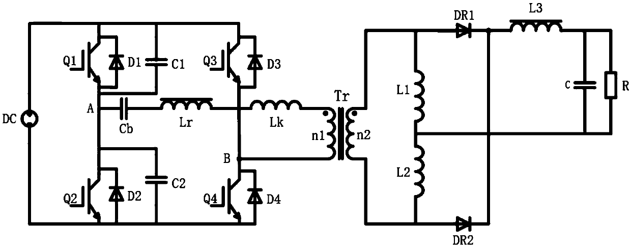
[0012] The specific implementation of this circuit is as follows:

[0013] Such as figure 1 As shown, the present invention uses a full-bridge inverter circuit and a current doubler rectification improved circuit topology to build, mainly including: a direct current power supply DC, a first switching tube Q1, a second switching tube Q2, a third switching tube Q3, and a fourth switching tube Tube Q4, first switching tube parallel capacitor C1, second switching tube parallel capacitor C2, first switching tube parallel diode D1, second switching tube parallel diode D2, third switching tube parallel diode D3, fourth switching tube parallel diode D4 , DC blocking capacitor Cb, saturated inductance Lr, transformer leakage inductance Lk, transformer Tr, transformer primary winding n1, transformer secondary winding n2, first inductance L1, second inductance L2, third inductance L3, first diode DR1, a second diode DR2, a filter capacitor C, and a load R.

[0014] The full-bridge inve...


PUM


Abstract

The invention relates to an improved current-doubling rectifying circuit, and relates to the technical field of power electronics, so that larger output current and smaller output voltage ripples canbe provided. The traditional current-doubling rectifying circuit has the following disadvantages that two output inductors are needed, the size is large, the mass is large, and the heights of two filtering inductors cannot be ensured, so that the currents flowing through two electric reactors are different to cause generation of magnetic biasing; and the development of the current-doubling rectifying circuit is hindered to a certain extent due to the abovementioned shortcomings. According to the invention, a traditional current-doubling circuit is improved, a magnetic inductor L3 is additionally arranged at the direct current end; two hollow windings are used by L2 and L1; and the total volume and the mass of the inductors are greatly reduced in an actual circuit, and the space is saved. Due to the fact that the inductance of the L1 and the inductance of the L2 are small, the inductance difference is very small in the manufacturing process, the differences of the passing-through currents are also very small, so that the problem of magnetic bias caused by the difference between the two electric reactors is solved.

Description

technical field [0001] The invention relates to the technical field of power electronics, in particular to a rectifier circuit. Background technique [0002] With the development of power electronics technology, rectifier circuits have been invented, which can convert alternating current into direct current, and are widely used. With the rapid development of switching power supply technology, communication power supplies require larger output current and smaller output voltage ripple, so current doubler rectification circuits are often used. However, the traditional current doubler rectifier circuit has the following disadvantages: two output inductors are required, which are large in size and high in quality; the height of the two filter inductors cannot be guaranteed to be consistent, so there will be differences in the current flowing through them, resulting in bias magnetization; The disadvantages have hindered the development of the current doubler rectifier circuit to...

Claims


Application Information

Patent Timeline
Patent Type & Authority Applications(China)
IPC IPC(8): H02M7/06
CPCH02M7/068
Inventor 黄鹏飞刘飞李滨胡伊通宋思琪卢振洋
Owner BEIJING UNIV OF TECH
Why Eureka
Try Eureka