Image inspection device, production system, image inspection method, program, and storage medium
An image inspection and image technology, applied in the direction of measuring devices, material analysis through optical means, instruments, etc., can solve the problems of high inspection devices, difficult additional costs, and a large number of steps
- Summary
- Abstract
- Description
- Claims
- Application Information
AI Technical Summary
Problems solved by technology
Method used
Image
Examples
no. 1 Embodiment approach
[0106] refer to Figure 1 to Figure 9 The image inspection device 1 according to the first embodiment of the present invention will be described.
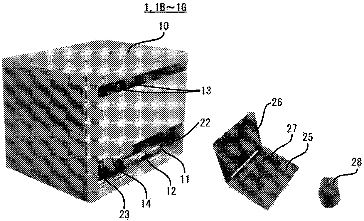
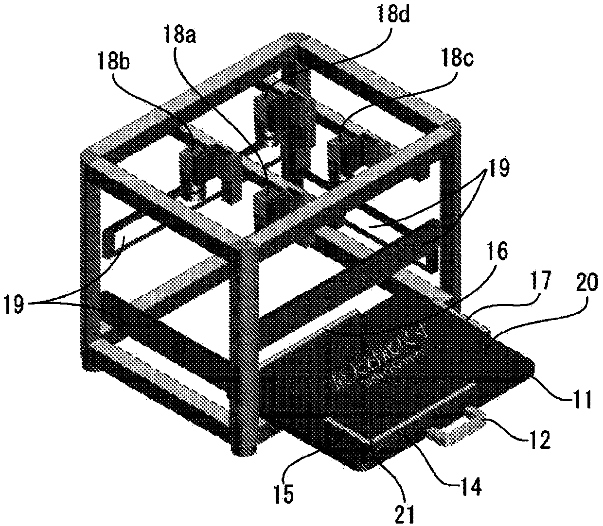
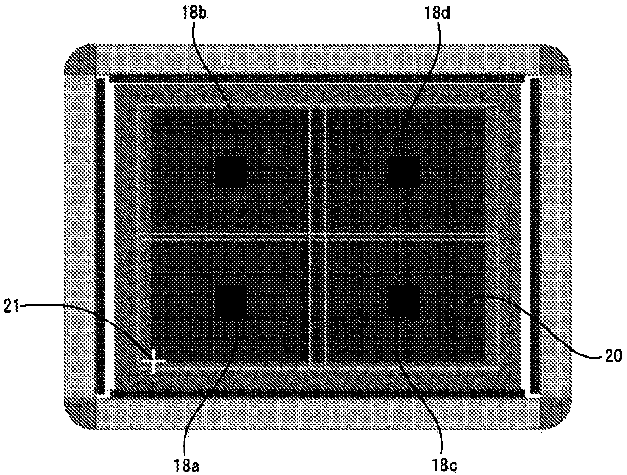
[0107] First, use Figure 1 ~ Figure 4 A schematic configuration of the image inspection apparatus 1 according to the first embodiment of the present invention will be described. also, figure 1 is an external perspective view of the image inspection device 1 according to the first embodiment of the present invention, figure 2 yes figure 1 perspective view of the image 3 It is an explanatory drawing of the shooting range of cameras 18a-18d, Figure 4 is a block diagram of the image inspection device 1 .
[0108]
[0109] The image inspection apparatus 1 is an apparatus for performing 2D image inspection, and includes an image inspection apparatus main body 10 and a personal computer main body (hereinafter referred to as “PC (Personal Computer, personal computer) main body”) 25 . The main body 10 of the image inspection ap...
no. 2 Embodiment approach
[0159] refer to Figure 10 An image inspection apparatus 1A according to a second embodiment of the present invention will be described. right with Figure 1 to Figure 9 The same symbols are assigned to the common configurations, and descriptions thereof are omitted. also, Figure 10 It is an external view of the image inspection apparatus 1A of the second embodiment.
[0160] The image inspection apparatus 1A of the second embodiment differs from the image inspection apparatus 1 of the first embodiment in that the PC main body 25 is incorporated into the image inspection apparatus main body 10A to be an all in one type. A PC main body 25 is assembled inside the image inspection apparatus main body 10A, and an LCD (Liquid Crystal Display, Liquid Crystal Display) monitor 26A is attached to the upper portion of the image inspection apparatus main body 10A via a monitor arm 57 . In addition, an indicator lamp 13A is provided on the front upper part of the image inspection app...
no. 3 Embodiment approach
[0164] An image inspection apparatus 1B according to a third embodiment of the present invention will be described. right with Figure 1 to Figure 10 The same symbols are assigned to the common configurations, and descriptions thereof are omitted. The image inspection apparatus 1B of the third embodiment differs from the image inspection apparatus 1 of the first embodiment in that the CAD data of the substrate 20 is used when the automatic grid 54 is acquired and / or when the reference image 40R is acquired.
[0165] First, a method of using the CAD data of the substrate 20 in automatic meshing 54 will be described. In the first embodiment, if the automatic grid 54 is selected, the grid of the standard [1] parameter is arranged in the necessary part by the automatic judgment of the system, but in the third embodiment, the PC main body 25 is preliminarily set The CAD data of the substrate 20 is stored, and the system can use the CAD data of the substrate 20 when the system aut...
PUM
 Abstract
Description
Claims
Application Information
 - R&D
- Intellectual Property
- Life Sciences
- Materials
- Tech Scout
- Unparalleled Data Quality
- Higher Quality Content
- 60% Fewer Hallucinations
Browse by: Latest US Patents, China's latest patents, Technical Efficacy Thesaurus, Application Domain, Technology Topic, Popular Technical Reports.
© 2025 PatSnap. All rights reserved.Legal|Privacy policy|Modern Slavery Act Transparency Statement|Sitemap|About US| Contact US: help@patsnap.com


