Travelling motor heat dissipating system

A technology of walking motor and heat dissipation system, which is applied in the combination of power unit cooling layout, power unit, transportation and packaging, etc., which can solve the problems of reduced motor life, reduced motor output, and poor cooling effect of the motor to achieve heat dissipation Improved performance, saving parts and space, and improved heat dissipation

Pending Publication Date: 2019-04-05
XCMG CONSTR MACHINERY
View PDF0 Cites 4 Cited by
  • Summary
  • Abstract
  • Description
  • Claims
  • Application Information

AI Technical Summary

Problems solved by technology

[0002] As an important power component of an electric drive unmanned vehicle, the motor has high requirements on the motor. Whether the motor is running normally or not depends on the heating degree of the motor. When the temperature of the motor is too high, it will not only hinder the normal operation of the parts, but also reduce the The output capacity of the motor is greatly reduced, and the life of the motor is also greatly reduced. In severe cases, the moving parts are stuck...

Method used


Image

  • Travelling motor heat dissipating system

Examples


Embodiment 1

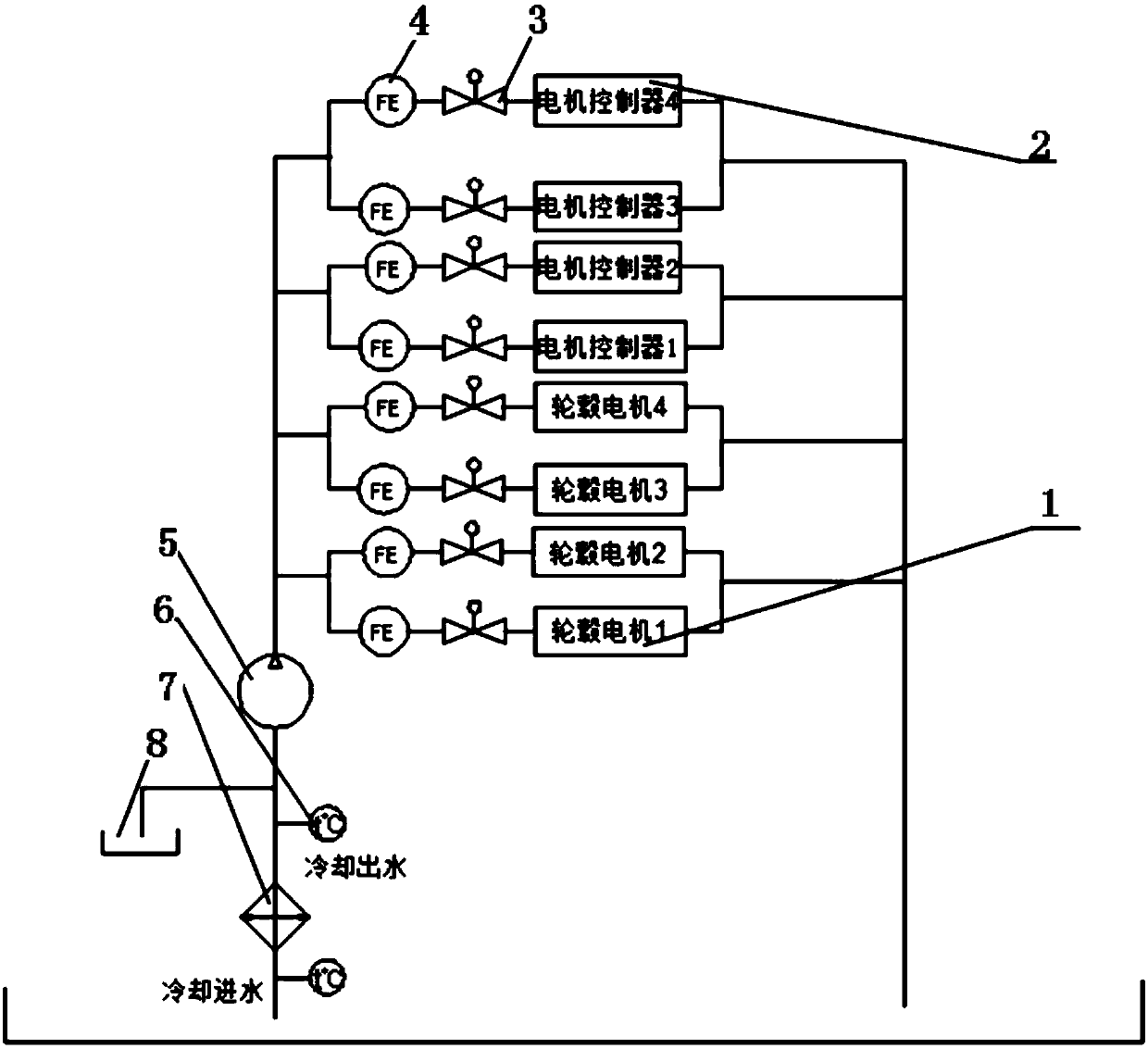
[0024] A walking motor heat dissipation system, the system adopts four sets of motors and four sets of motor controllers connected in parallel, under the premise of the same motor, motor controller, water pump, radiator, etc., the heat dissipation capacity of the motor should be significantly improved, and at the same time A flow meter and an electric ball valve are installed on each parallel waterway to adjust the flow in each branch in real time, so that the heat dissipation effect of the walking motor is significantly improved.

[0025] Use one water pump to provide coolant for four motors and motor controllers at the same time, which saves the number of structural parts. Four motors and four motor controllers are connected in parallel, so that the walking motor, motor controller, water pump, radiator, etc. are the same Under the premise, the heat dissipation capacity of the motor is significantly improved. Electric ball valves and flow meters are connected to the pipeline b...

Embodiment 2

[0046] A heat dissipation method for a traveling motor, characterized in that it comprises:

[0047] Obtain the temperature signal of the water outlet of the radiator, and control the speed of the fan of the radiator based on the temperature signal of the water outlet of the radiator; When the temperature is higher than a certain set temperature, the fan is turned on at full speed, and the speed regulation method of the fan is linear smooth speed change, stepless speed change;

[0048] Obtain the flow signal in each branch, and when the flow value in the branch is greater than the preset value, send a signal to the electric ball valve in the branch, and the electric ball valve will reduce the opening size according to the flow signal provided by the flowmeter. Similarly, When the flowmeter detects that the flow in the branch is less than the preset value, it sends a signal to the electric ball valve in the branch, and the electric ball valve increases the opening size accordin...


PUM


Abstract

The invention discloses a travelling motor heat dissipating system. The travelling motor heat dissipating system comprises travelling motors, motor controllers, an electronic control water pump, a heat dissipater assembly and an expanding water tank; an inlet of the electronic control water pump is connected with a water outlet of the heat dissipater assembly and a water outlet of the expanding water tank through pipelines; a parallel connection manner is adopted between the travelling motors and the motor controllers, and the travelling motors and the motor controllers are both connected withan outlet of the electronic control water pump; electric ball valves and flow meters are arranged among the travelling motors, the motor controllers and the electronic control water pump; the four sets of motors and the four sets of motor controllers are correspondingly connected in parallel, and on the premise that the motors, the motor controllers, the water pump, the heat dissipater and the like are the same, the heat dissipating capacity of the motors is obviously improved; and meanwhile, one flow meter and one electric ball valve are assembled on each water way in parallel connection sothat the flow in each branch way is adjusted in real time, and the heat dissipating effect of the travelling motors is obviously improved.

Description

technical field [0001] The invention belongs to the technical field of ground unmanned vehicles, and relates to a cooling system for a walking motor. Background technique [0002] As an important power component of an electric drive unmanned vehicle, the motor has high requirements on the motor. Whether the motor is running normally or not depends on the degree of heating of the motor. When the temperature of the motor is too high, it will not only hinder the normal operation of the parts, but also reduce the The output capacity of the motor is too low, so that the life of the motor is also greatly reduced, and in severe cases, the moving parts are stuck, resulting in potential safety hazards. [0003] The prior art has the following defects: (1) In the prior art, the motor is connected in series behind the motor controller, and the cooling effect of the motor is relatively poor. [0004] (2) When the left motor and the right motor in the heat dissipation system are connect...

Claims


Application Information

Patent Timeline
IPC IPC(8): B60K11/04
CPCB60K11/04
Inventor 郭振华谢德杰鲁振
Owner XCMG CONSTR MACHINERY
Why Eureka
Try Eureka