Curtain wall adjustable connection joint structure based on transformation angle iron and construction method
A technology for connecting joints and angle steels, which is applied in the direction of building structures, walls, and building components, and can solve problems such as difficulty in eliminating additional stress and construction errors, complex structures and shapes, and different directions and sizes of stress and deformation. Achieve the effects of strong adjustability, reasonable structural design, and elimination of accumulated construction errors
- Summary
- Abstract
- Description
- Claims
- Application Information
AI Technical Summary
Problems solved by technology
Method used
Image
Examples
Embodiment 1
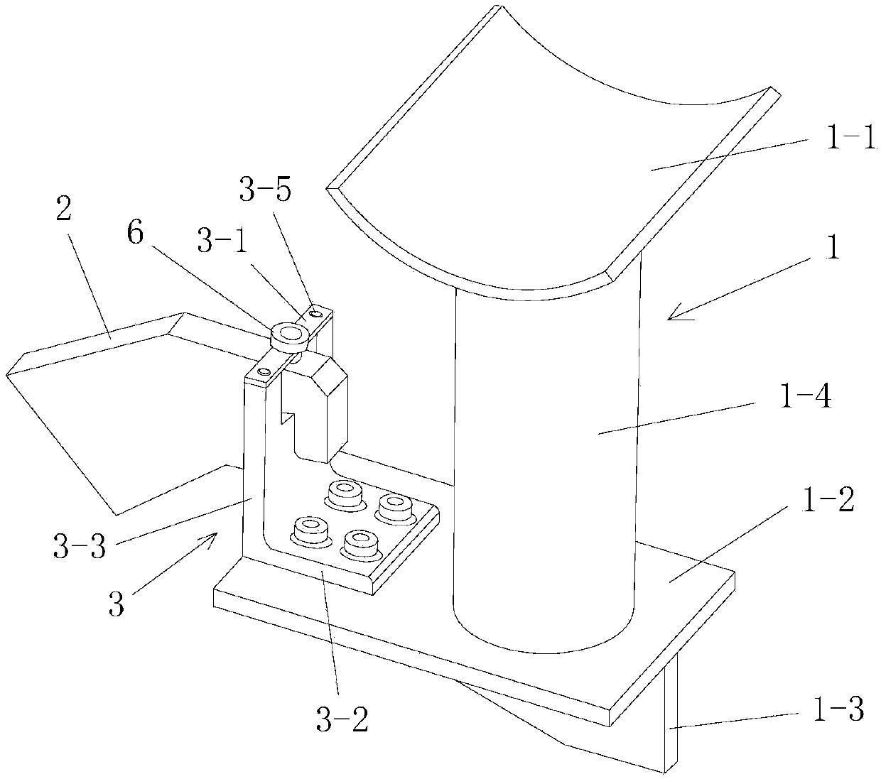
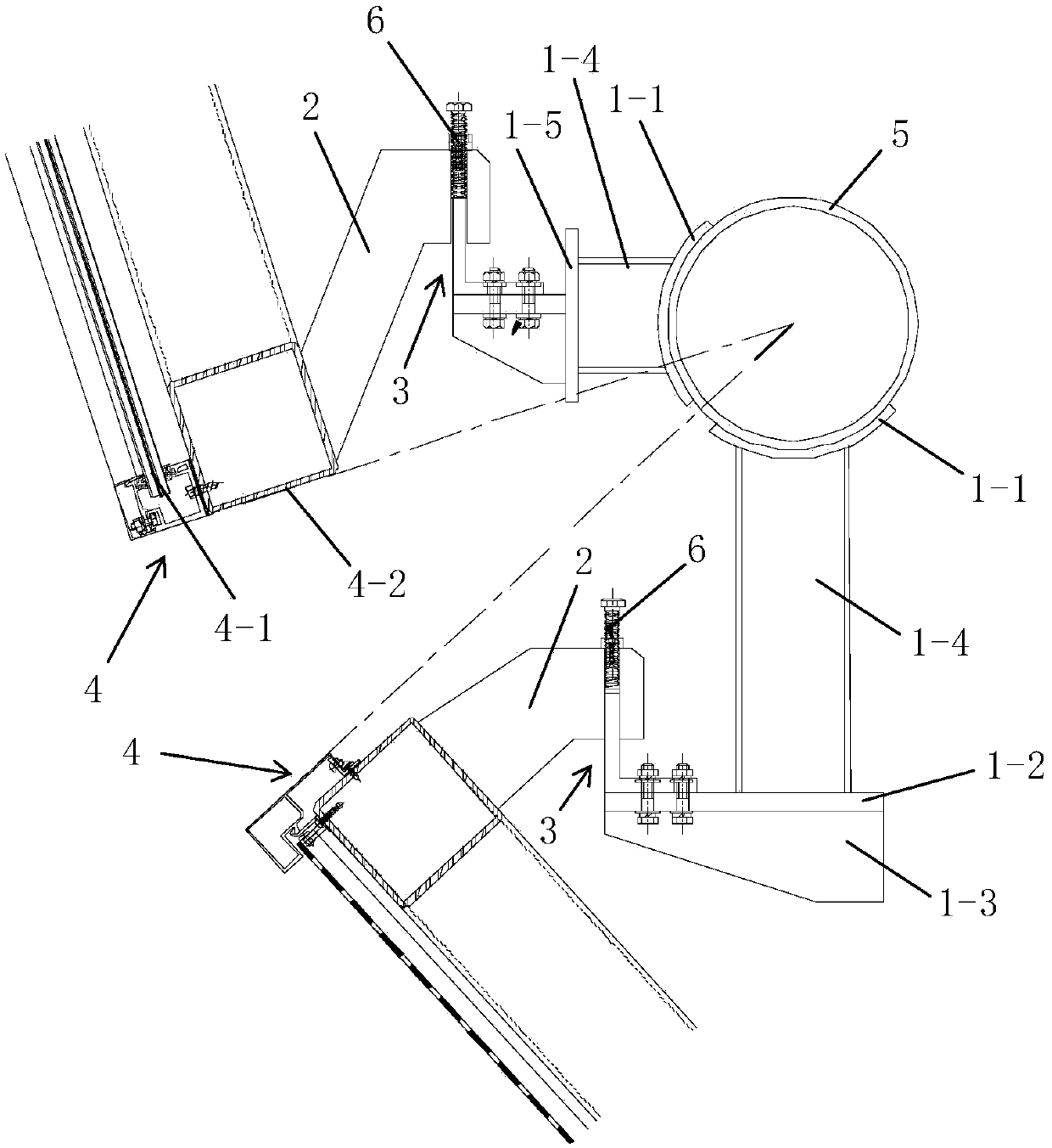
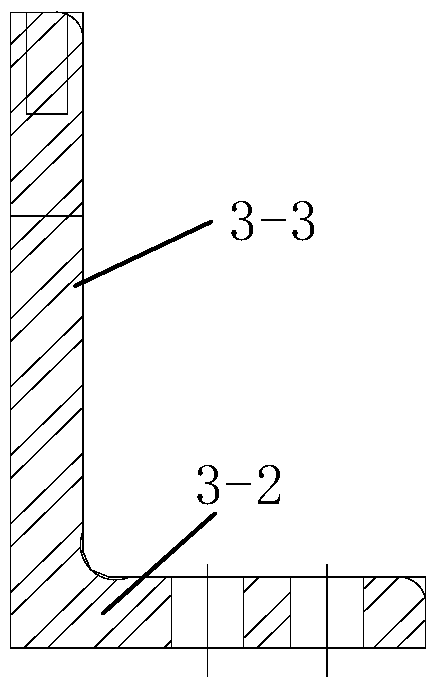
[0066] Such as figure 1 , figure 2 The shown one based on the conversion angle steel curtain wall adjustable connection node structure, including the fixed support 1 fixed on the curtain wall support structure and the conversion angle steel 3 fixed by the connection hook 2 installed on the curtain wall panel, the curtain wall panel is located at the The outer side of the curtain wall support structure; the number of fixed conversion angle steel 3 on the fixed support 1 is one; the curtain wall panel is spliced by a plurality of curtain wall units 4, and each of the curtain wall units 4 is provided with a connecting hook inside 2. Each of the connection hooks 2 is fixed on one of the conversion angles 3 located inside; the fixed support 1 includes a base 1-1 fixed on the curtain wall support structure and a base 1-1 1, the conversion angle steel 3 is fixed on the support structure; the conversion angle steel 3 includes the angle steel body for hooking the connection hook 2 ...
Embodiment 2
[0136] Such as Figure 7 , Figure 8 As shown, in this embodiment, the difference between the curtain wall adjustable connection node structure adopted and Embodiment 1 is that: the number of angle steel connection plates 1-2 in the support structure is multiple; the rigid support also includes a welding An intermediate connecting steel plate 1-5 fixed on the vertical support 1-4, each of the angle steel connecting plates 1-2 and the vertical supporting 1-4 is connected through the intermediate connecting steel plate 1-5. The intermediate connecting steel plate 1-5 is a straight steel plate, and the angle steel connecting plate 1-2 is welded and fixed on the intermediate connecting steel plate 1-5. In this way, the simple, fast and reliable connection requirements of multiple angle steel connecting plates 1-2 can be met, and the purpose of fixing multiple conversion angle steels 3 on the same fixed support 1 can be satisfied, the use mode is flexible, and the fixed support 1 ...
Embodiment 3
[0142] Such as Figure 9 with Figure 10 As shown, in this embodiment, the structure of the adjustable connection node of the curtain wall adopted is different from that of Embodiment 1 in that: the front and rear adjustment bolts 7 that drive the connection hook 2 to move back and forth are installed on the hook section of the connection hook 2 , the front and rear adjusting bolts 7 are arranged parallel to the insertion section and the hooking section is arranged vertically; the front and rear adjusting bolts 7 are arranged on the same plane as the upper and lower adjusting bolts 6, and the front and rear adjusting bolts 7 Arranged on the central axis of the hooking section, the hooking section is provided with adjusting bolt mounting holes for the front and rear adjusting bolts 7 to be installed; the front and rear adjusting bolts 7 installed on the connecting hook 2 and the hooked The hooking side 3-3 is vertically arranged, and the front end of the front and rear adjusti...
PUM
 Abstract
Description
Claims
Application Information
 - R&D
- Intellectual Property
- Life Sciences
- Materials
- Tech Scout
- Unparalleled Data Quality
- Higher Quality Content
- 60% Fewer Hallucinations
Browse by: Latest US Patents, China's latest patents, Technical Efficacy Thesaurus, Application Domain, Technology Topic, Popular Technical Reports.
© 2025 PatSnap. All rights reserved.Legal|Privacy policy|Modern Slavery Act Transparency Statement|Sitemap|About US| Contact US: help@patsnap.com


