Eureka AIR delivers breakthrough ideas for toughest innovation challenges, trusted by R&D personnel around the world.

Improved cooling tower

A cooling tower and main frame technology, applied in the field of cooling towers, can solve the problems of power consumption, poor cooling effect of cooling towers, low cooling efficiency, etc., achieve high cooling efficiency, improve efficiency, and improve production efficiency

Inactive Publication Date: 2019-04-05
蒋玉高
View PDF0 Cites 0 Cited by
  • Summary
  • Abstract
  • Description
  • Claims
  • Application Information

AI Technical Summary

Problems solved by technology

[0002] A cooling tower is a device that uses water as a circulating coolant to absorb heat from a system and discharge it to the atmosphere to lower the water temperature; its cooling is to use water and air to exchange heat and cold to generate steam, and the steam evaporates to take away heat to achieve evaporation The principle of heat dissipation, convective heat transfer and radiation heat transfer is used to dissipate the waste heat generated in industry or in refrigeration and air conditioning to reduce the water temperature. The evaporative cooling device is used to ensure the normal operation of the system. The device is generally barrel-shaped, so it is called a cooling tower; Traditional cooling towers have poor cooling effect and cannot fully combine water cooling and air cooling, resulting in low cooling efficiency and power consumption

Method used


Image

  • Improved cooling tower

Examples


Embodiment Construction

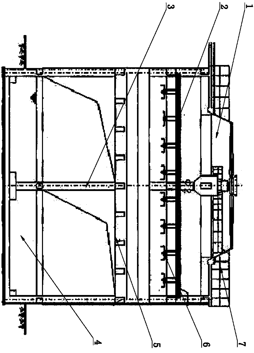
[0014] The purpose of the present invention is achieved as follows: an improved cooling tower, including a main frame, the main frame is arranged longitudinally, characterized in that the main frame is divided into an upper part, a middle part and a lower part, and the upper part is provided with a fan 1. The fan 1 is directly arranged at the top of the main frame, the fan 1 is driven by a driving device 7, and the driving device 7 is fixed on the top of the main frame, and the main frame is provided with a main shaft 3 from top to bottom; The middle part is provided with a cooling spray system. The cooling spray system includes several groups of spray pipes 2, and several groups of nozzles 6 are arranged on the spray pipes 2, and a cooling table is arranged below the spray system. , The cooling workbench is provided with several sets of baffles, the cooling workbench is directly fixed on the main frame, and the cooling workbench is supported by the main shaft 3; between the spr...


PUM


Abstract

The invention relates to an improved cooling tower in the field of cooling towers. A main frame comprises an upper part, a middle part and a lower part; a fan is arranged on the upper part, is directly arranged at the top end of the main frame, and is driven by a drive device; the drive device is fixed to the top end of the main frame; the main frame is provided with a main shaft from top to bottom; a cooling spraying system is arranged in the middle of the main frame and comprises multiple groups of spraying pipes; multiple groups of nozzles are arranged on the spraying pipes; a cooling working table is arranged under the spraying system in a matching way; multiple groups of baffle plates are arranged on the cooling working table; the cooling working table is directly fixed onto the mainframe; the middle of the cooling working table is supported through the main shaft; a material inlet and a material outlet are formed between the spraying system and the cooling working table; and animpounding reservoir is arranged on the lower part and is provided with a water inlet and a water outlet. The improved cooling tower provided by the invention can be used for quickly cooling materialsto be cooled, and a water cooling system and an air cooling system are matched for comprehensively cooling omnidirectionally, so that the improved cooling tower is high in cooling efficiency, simpleand easy to use.

Description

Technical field [0001] The invention relates to an improved cooling tower in the field of cooling towers. Background technique [0002] A cooling tower is a device that uses water as a circulating coolant to absorb heat from a system and discharge it into the atmosphere to reduce the temperature of the water; its cooling is to use water and air to flow in contact with each other to exchange cold and heat to produce steam, and the steam volatilizes to take away heat to achieve evaporation The principle of heat dissipation, convection heat transfer and radiation heat transfer is an evaporative heat dissipation device that reduces the water temperature by dissipating the waste heat generated in the industry or in refrigeration and air conditioning to ensure the normal operation of the system. The device is generally barrel-shaped, so it is called a cooling tower; The traditional cooling tower has poor cooling effect and cannot completely combine water cooling and wind cooling, resul...

Claims


Application Information

Patent Timeline
IPC IPC(8): F25D1/02F25D17/02
CPCF25D1/02F25D17/02
Inventor 蒋玉高
Owner 蒋玉高
Why Eureka
Eureka Blog
Learn More