
Composite silicon-based waveguide structure and preparation method thereof

A waveguide structure and silicon-based technology, applied in the field of optical waveguides, can solve problems such as waveguide transmission loss, achieve the effects of reducing refractive index difference, high optical nonlinear threshold, and reducing waveguide transmission loss

Pending Publication Date: 2019-04-05
CHINA SCI PHOTON CHIP HAINING TECH CO LTD
View PDF12 Cites 1 Cited by
  • Summary
  • Abstract
  • Description
  • Claims
  • Application Information

AI Technical Summary

Problems solved by technology

[0005] Therefore, in order to overcome the problem of certain loss in waveguide transmission in the prior art, a composite silicon-based waveguide structure that reduces waveguide transmission loss and realizes low-loss transmission is provided.

Method used


Image

  • Composite silicon-based waveguide structure and preparation method thereof
  • Composite silicon-based waveguide structure and preparation method thereof
  • Composite silicon-based waveguide structure and preparation method thereof

Examples


Embodiment 1

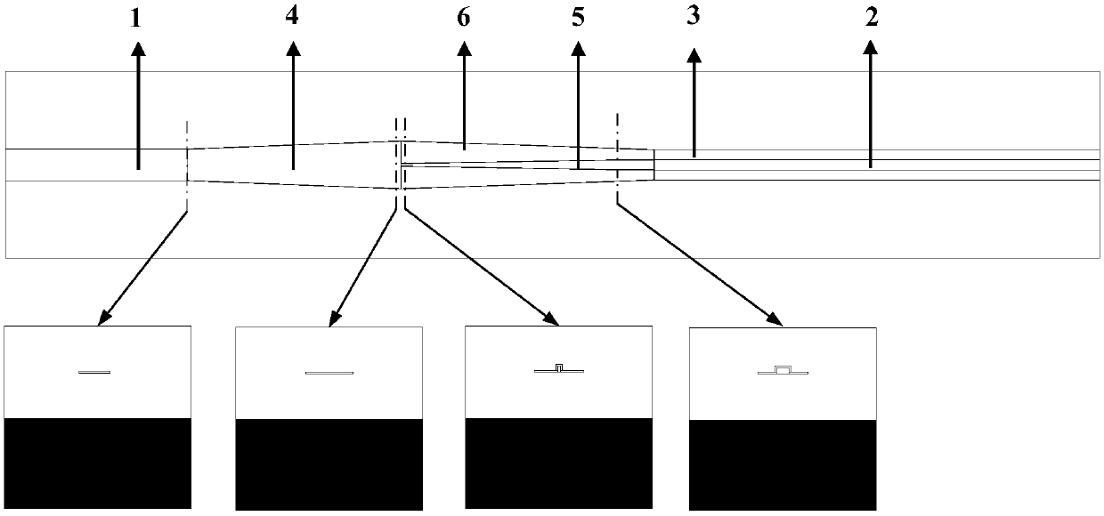
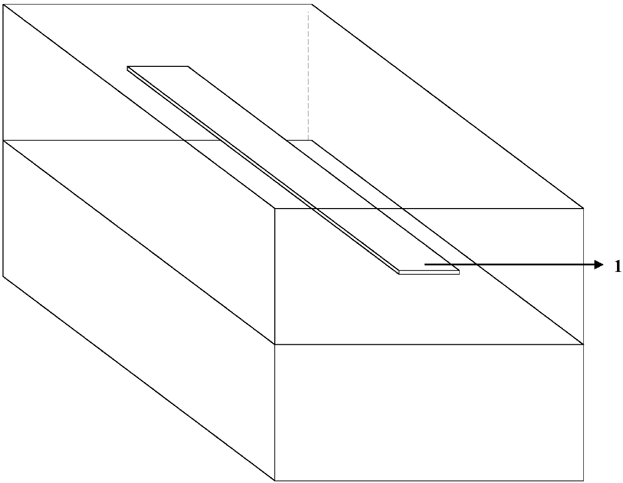
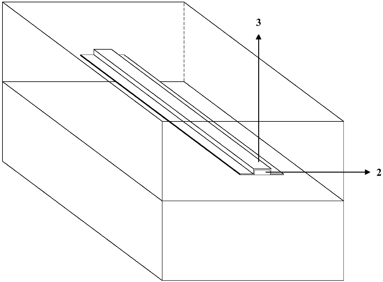
[0037] figure 1 It shows a composite silicon-based waveguide structure provided by the present invention, including: a weakly bound waveguide, such as figure 2 As shown, the first core layer 1 is included, and the first core layer 1 matches the mode field diameter of the weakly bound waveguide; the strongly bound waveguide, such as image 3 As shown, the second core layer 2 and the third core layer 3 covering the top and sidewalls of the second core layer 2 are included; the spot conversion structure, such as Figure 4 As shown, it includes a weakly bound part and a strong bound part connected to the weakly bound waveguide and the strongly bound waveguide respectively; the weakly bound part and the strong bound part are respectively connected to the weakly bound waveguide and the The strong confinement waveguide conforms to the waveguide structure. Through layered patterning, two waveguide structures can be formed on the chip, a weakly bound waveguide and a strongly bound w...

Embodiment 2

[0043] A preparation method of a composite silicon-based waveguide structure, the film of the second core layer 2 is placed on the substrate layer and the lower cladding layer, and the pattern photolithography is carried out, and the second core layer 2 is dry etched; on the second core layer 2, using a chemical vapor deposition method to make a thin film of the first core layer 1; performing pattern photolithography on the thin film of the first core layer 1, and dry etching the first core layer 1; on the first core layer 1 The upper cladding layer is fabricated by chemical vapor deposition. The pattern photolithography is ultraviolet gray scale photolithography.

[0044] It should be pointed out that if it is necessary to fabricate the gradient structure, it also includes using photolithography to fabricate the gradient structure before patterning the thin film of the second core layer 2 .

[0045] It should be pointed out that the pattern lithography can also be electron b...


PUM


Abstract

The invention provides a composite silicon-based waveguide structure. The composite silicon-based waveguide structure comprises a weakly-bound waveguide, a strongly-bound waveguide, a spot-size conversion structure, wherein the weakly-bound waveguide comprises a first core layer, the first core layer is matched with the mode field diameter of the weakly-bound waveguide; the strongly-bound waveguide comprises a second core layer and a third core layer covering the top and the side wall of the second core layer; the spot-size converter comprises a weakly-bound part and a strongly-bound part which are interconnected and communicate with the weakly-bound waveguide and the strongly-bound waveguide correspondingly; the weakly-bound part and the strongly-bound part are waveguide structures whichare consistent with the weakly-bound waveguide and the strongly-bound waveguide correspondingly.

Description

technical field [0001] The invention relates to the field of optical waveguide technology, in particular to a composite silicon-based waveguide structure and a preparation method thereof. Background technique [0002] In the existing silicon-based optical integrated chip structure, common waveguide core materials are single crystal silicon, doped silicon dioxide, silicon nitride, silicon oxynitride, etc.; common waveguide cladding materials are prepared by thermal oxidation, PECVD or LPCVD methods Silicon oxide layer, or doped silicon oxide layer. Among them, core layers such as silicon and silicon nitride with a relatively high refractive index facilitate the preparation of small mode field waveguides, and have a small bending radius, making the chip have a high degree of integration. [0003] The mode field diameter of the standard single-mode fiber in the communication band C-Band is in the range of 4um-10um, while the typical value of the mode field diameter of the sili...

Claims


Application Information

Patent Timeline
Patent Type & Authority Applications(China)
IPC IPC(8): G02B6/122G02B6/14G02B6/132G02B6/136
CPCG02B6/122G02B6/132G02B6/136G02B6/14G02B2006/12176G02B2006/12173G02B2006/12061
Inventor 刘敬伟李文玲田立飞张新群
Owner CHINA SCI PHOTON CHIP HAINING TECH CO LTD
Learn More