A resistance sensing type capacitor commutation hybrid current limiter and a control method thereof

A current limiter and hybrid technology, applied in the field of power electronics, can solve the problems of high loss of solid-state DC current limiter, high manufacturing cost of superconducting current limiter, large equipment volume, etc., achieve good current limiting effect and save investment , The effect of small loss resistance

Inactive Publication Date: 2019-04-05
NORTH CHINA ELECTRIC POWER UNIV (BAODING)
View PDF12 Cites 5 Cited by
  • Summary
  • Abstract
  • Description
  • Claims
  • Application Information

AI Technical Summary

Problems solved by technology

[0005] In order to overcome the problems of high loss and poor economy of the solid-state DC current limiter in the above-mentioned prior art, as well as the high manufacturing cost and large equipment volume of the superconducting current limiter, the present invention provides a hybrid current limiter of resistive-inductive capacitive commutation and its control method, the resistive-inductive capacitive commutation hybrid current limiter includes an on-state low-loss branch, a current transfer branch and a current-limiting branch

Method used


Image

  • A resistance sensing type capacitor commutation hybrid current limiter and a control method thereof
  • A resistance sensing type capacitor commutation hybrid current limiter and a control method thereof
  • A resistance sensing type capacitor commutation hybrid current limiter and a control method thereof

Examples


Embodiment 1

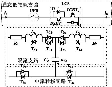
[0043] Embodiment 1 of the present invention provides a resistive-inductive capacitive commutation hybrid current limiter, which specifically includes an on-state low-loss branch, a current transfer path, and a current-limiting branch. The functions of each branch are as follows:

[0044] The on-state low-loss branch is used to realize the conduction of the steady-state current of the DC line when the DC line is running normally, and transfer the fault current to the current-limiting branch after detecting a fault in the DC line;

[0045] Among them, the current transfer branch is used to carry the fault current transferred by the flow-through branch, and force the current-limiting element in the current-limiting branch to connect to the DC line;

[0046] Among them, the current-limiting branch is used to increase the system damping and reduce the rising speed of the fault current after being connected in series with the DC line.

[0047] The structure diagram of the resistive...

Embodiment 2

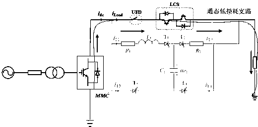
[0053] Embodiment 2 of the present invention provides a control method for a resistive-inductive capacitive commutation hybrid current limiter, the specific process is as follows:

[0054] When the DC line where the resistive-inductive capacitive commutation hybrid current limiter is located is in normal operation, the thyristors in the current transfer branch are all turned off, the current limiting branch is out of operation, and the IGBT in the on-state low-loss branch 1 and IGBT 2 conduction, the steady-state current flows through the flow-through branch, and the schematic diagram of the steady-state current flow path when the DC line is in normal operation is shown in figure 2 shown.

Embodiment 3

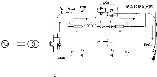
[0056] The control method of the resistive-inductive capacitive commutation hybrid current limiter provided in Embodiment 3 of the present invention, the specific process is as follows:

[0057] Before detecting a fault on the DC line where the resistive-inductive capacitive commutation hybrid current limiter is located, the IGBT in the current branch 1 and IGBT 2 is turned on, the fault current flows through the on-state low-loss branch, and the schematic diagram of the flow path of the DC line fault current before the fault is detected is shown in image 3 shown.


PUM


Abstract

The invention provides a resistance sensing type capacitor commutation hybrid current limiter and a control method thereof. The hybrid current limiter includes an on-state low-loss branch, a current-transfer branch and a current-limiting branch. The hybrid current limiter adopts a half-controlled device, is simple in logic, and is economical and reliable. The current limiter has low steady-state loss and has bidirectional current limiting capability, which can effectively suppress the short-circuit current of a DC grid and reduce the dissipated energy of a lighting arrester. The current limiter greatly delays the blocking time of a sub-module IGBT, and obtains sufficient time for the remaining protection devices. The use of half-controlled power electronic device can save the parallel number of power electronic devices and save costs, and ensure that a current limiting resistor and corresponding heat sinks are fully utilized to improve the current limiting effect. The control method ofthe resistance sensing type capacitor commutation hybrid current limiter provided by the invention realizes the control of the resistance sensing type capacitor commutation hybrid current limiter ina condition when a DC line where the current limiter is located operates normally or in a condition before or after the DC line where the resistance sensing type capacitor commutation hybrid current limiter is located is disconnected.

Description

technical field [0001] The invention relates to the technical field of power electronics, in particular to a resistance-inductance capacitive commutation hybrid current limiter and a control method thereof. Background technique [0002] High-voltage and large-capacity DC grid technology is an important link in the future construction of smart grids and global energy Internet. Flexible DC transmission technology based on modular multilevel converter (MMC) facilitates the construction of DC power grids, thus becoming a new expectation in the power industry. my country's upcoming Zhangbei DC power grid adopts the half bridge sub module plus overhead line scheme, which is the world's first DC power grid engineering practice. The use of overhead lines has obvious technical and economic advantages, but the ensuing problem is the high probability of faults on the DC side. Combined with the fact that the half-bridge sub-module does not have the ability to clear faults on the DC sid...

Claims


Application Information

Patent Timeline
Patent Type & Authority Applications(China)
IPC IPC(8): H02H9/02
CPCH02H9/02
Inventor 赵西贝徐建中宋冰倩赵成勇
Owner NORTH CHINA ELECTRIC POWER UNIV (BAODING)
Why Eureka
Try Eureka