
Hot pipe with incondensable gas

A technology of gas and heat pipes, which is applied in the field of heat pipes with non-condensable gases, can solve the problems that electronic components cannot reach the working temperature smoothly, and electronic components cannot work efficiently, so as to achieve the effect of increasing practicability and improving work efficiency

Active Publication Date: 2019-04-05
CELSIA TECH TAIWAN INC
View PDF4 Cites 0 Cited by
  • Summary
  • Abstract
  • Description
  • Claims
  • Application Information

AI Technical Summary

Problems solved by technology

However, in a special use environment (such as an extremely cold environment), the good heat transfer efficiency of the heat pipe will cause the electronic components to fail to reach the proper working temperature, so that the electronic components cannot exert their maximum working performance

Method used


Image

  • Hot pipe with incondensable gas
  • Hot pipe with incondensable gas
  • Hot pipe with incondensable gas

Examples


Embodiment Construction

[0014] The detailed description and technical content of the present invention are described below with the accompanying drawings, but the attached drawings are only for reference and illustration, and are not intended to limit the present invention.

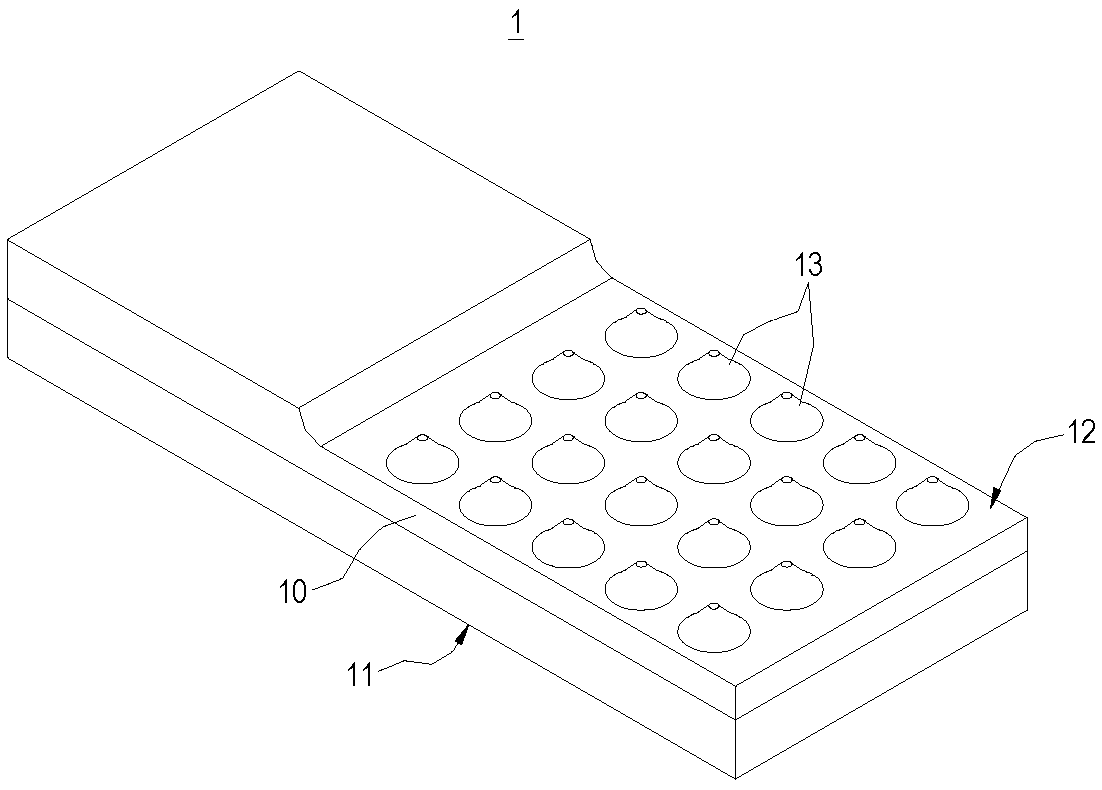
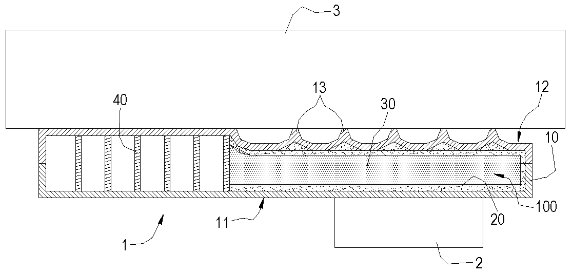
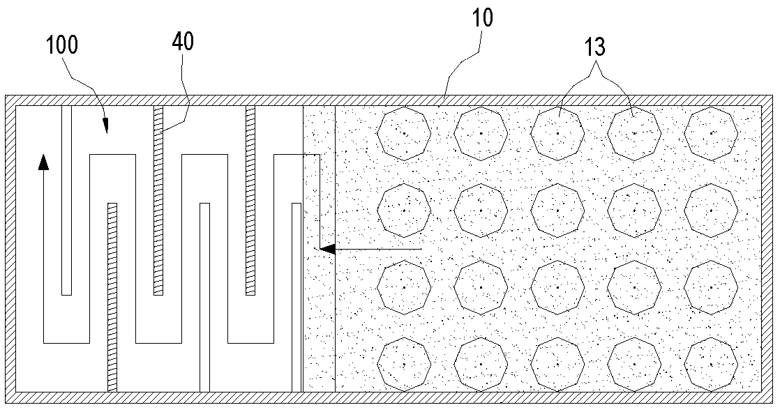
[0015] refer to Figure 1 to Figure 3 Shown are the three-dimensional appearance schematic diagram, the use schematic diagram and the cross-sectional schematic diagram of the heat pipe with non-condensable gas of the present invention, respectively. Such as figure 1 and 2 As shown, the heat pipe 1 with noncondensable gas of the present invention is used to dissipate heat from a heat-generating electronic component 2 ; preferably, the heat pipe 1 with noncondensable gas is also combined with a heat sink 3 . In an embodiment of the present invention, the heat sink 3 is a set of heat dissipation fins.

[0016] refer to figure 2 and image 3 As shown, in this embodiment, the heat pipe 1 with noncondensable gas includes a heat ...


PUM


Abstract

The invention discloses a hot pipe with an incondensable gas. The hot pipe comprises a heat conductor, a working fluid and the incondensable gas, wherein the working fluid and the incondensable gas are filled in a hollow cavity of the heat conductor, the heat conductor is provided with a heat absorption side and a heat releasing side, the heat absorption side is connected with a heating electronicassembly in a contact way, the heat releasing side is connected with a cooling body in a heat conduction way, at least one convex part is formed at the heat releasing side, and the contact area of the cooling body can be reduced by the arrangement of the convex part at the heat releasing side. By the hot pipe with the incondensable gas, the conduction efficiency is reduced by the incondensable gas and the convex part, the hot pipe runs under a working temperature zone, so that the working efficiency of the heating electronic assembly is achieved.

Description

technical field [0001] The invention relates to a heat pipe technology, in particular to a heat pipe with non-condensable gas. Background technique [0002] The working principle of a general heat pipe (Heat Pipe) is to provide a phase change of the working fluid injected into it through the internal vacuum environment to transfer heat after being heated, and then the working fluid returns to a liquid state after being cooled and can be refluxed and circulated Reuse, its implementation method is to attach the evaporation end surface of the heat pipe to the surface of the electronic heating component, so that the heat energy generated by the electronic component is absorbed through the evaporation end surface of the heat pipe, and then transferred to the radiator through the heat pipe to achieve the effect of heat dissipation. [0003] The internal vacuum state of the traditional heat pipe structure is to remove the non-condensable gas in the pipe, so as to improve the heat t...

Claims


Application Information

Patent Timeline
Patent Type & Authority Applications(China)
IPC IPC(8): H05K7/20F28D15/02
CPCF28D15/02F28D2021/0028H05K7/20336
Inventor 乔治麦尔孙建宏
Owner CELSIA TECH TAIWAN INC
Learn More