
Pipe fitting composite forming device

A technology of composite forming and pipe fittings, which is applied in the field of metal material processing and forming, and can solve problems such as failure

Active Publication Date: 2019-04-09
XIANGTAN UNIV
View PDF5 Cites 4 Cited by
  • Summary
  • Abstract
  • Description
  • Claims
  • Application Information

AI Technical Summary

Problems solved by technology

[0004] In order to solve the problem that the existing high-pressure forming of pipe fittings is prone to failure in the form of wrinkling, buckling and cracking, the invention proposes a composite forming device for pipe fittings

Method used


Image

  • Pipe fitting composite forming device
  • Pipe fitting composite forming device
  • Pipe fitting composite forming device

Examples


Embodiment

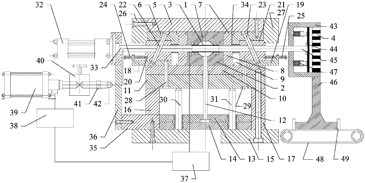
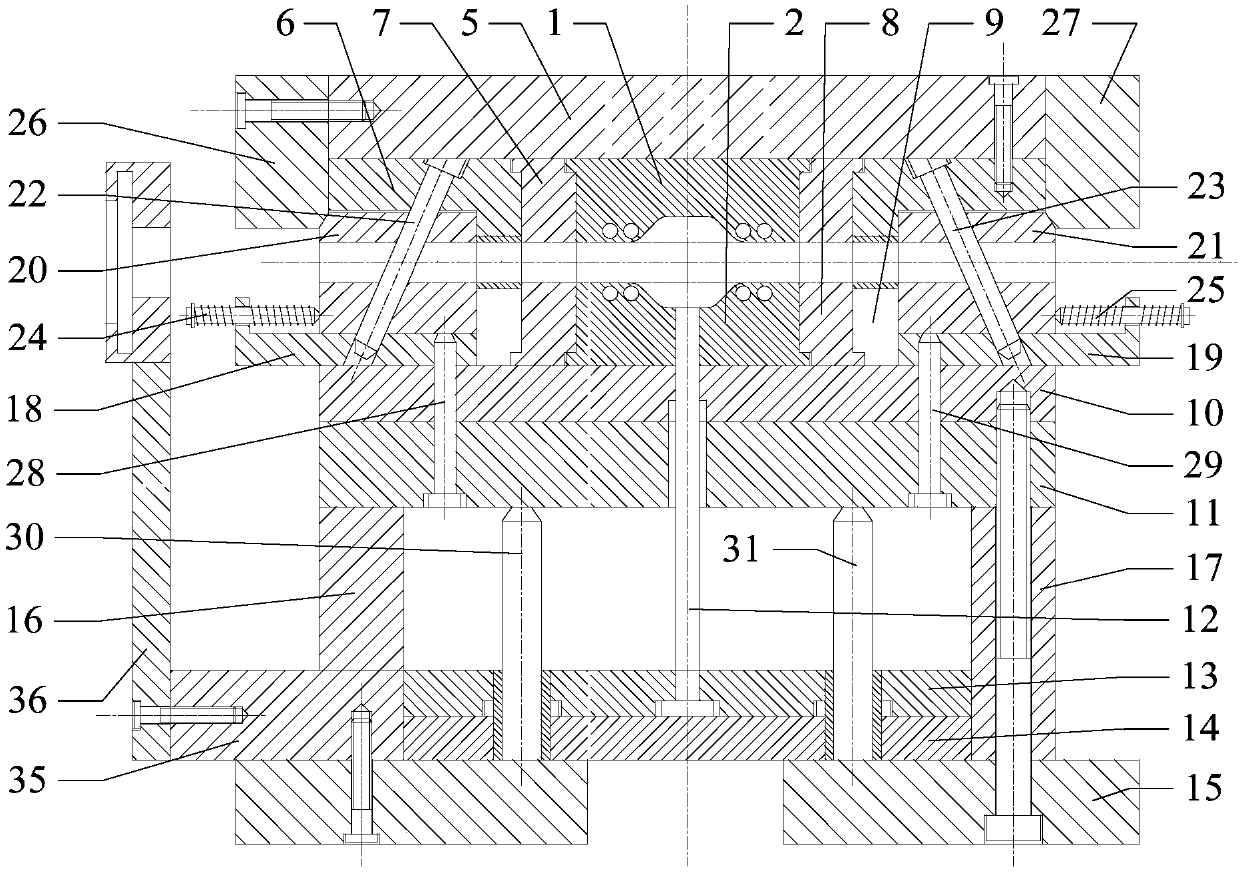
[0087] Embodiment: combine below Figure 1 to Figure 31 This embodiment will be described in detail.

[0088] The composite pipe forming device described in this embodiment includes a combined mold unit, a heating unit, a hydraulic unit, an axial feeding unit, an electromagnetic pulse generating unit and an impact unit;

[0089] The combined mold unit comprises an upper die 1 and a lower die 2, and an upper cavity is set indented on the bottom surface of the upper die 1, and a lower cavity is set indented on the top surface of the lower die 2, and the upper die 1 and the lower die 2 are vertically opposed and fixed, and the pipe fitting 3 to be formed is clamped horizontally between the upper die 1 and the lower die 2, and the upper cavity and the lower cavity together form the cavity of the combined mold unit;

[0090] The heating unit is used to heat the pipe fitting 3 to a predetermined temperature;

[0091] The hydraulic unit is used to inject the emulsion into the pipe ...


PUM


Abstract

The invention relates to a pipe fitting composite forming device, and belongs to the field of metal material processing and forming. The pipe fitting composite forming device solves the problem that efficiency losing in the manner of wrinkling, buckling, cracking and the like is prone to being caused by high pressure forming in an existing pipe fitting. The pipe fitting composite forming device ischaracterized in that an upper cavity and a lower cavity are arranged in the bottom surface of an upper die and the top surface of the lower die in a sinking manner correspondingly, a cavity of a combined die unit is formed by the upper cavity and the lower cavity, and a pipe fitting to be formed is horizontally clamped between the upper die and the lower die. A heating unit is used for heating the pipe fitting to a predetermined temperature. A hydraulic unit is used for injecting emulsion into the pipe fitting reaching the predetermined temperature to enable the pipe fitting to reach a deformation critical point, and the emulsion is recovered after the pipe fitting is formed. An axial feeding unit is used for applying axial pressure to the pipe fitting at the deformation critical point to wrinkle the outer wall of the pipe fitting. An impact unit is used for applying impact force to the pipe fitting with the wrinkling outer wall through the emulsion in the pipe fitting under the effect of an electromagnetic pulse generating unit until the pipe fitting is attached to the cavity of the combined mold unit.

Description

technical field [0001] The invention relates to a pipe fitting forming device, which belongs to the field of metal material processing and forming. Background technique [0002] Internal high pressure forming, also called hydroforming or hydroforming, is a material forming process that uses liquid as a forming medium to form hollow parts by controlling internal pressure and material flow. Compared with the existing material forming processes such as stamping and welding, internal high pressure forming has many advantages such as fewer molds, fewer parts forming steps, high material utilization rate and effective improvement of parts performance. With the application of advanced control technology on internal high pressure forming equipment, internal high pressure forming has become a flexible, controllable, safe and efficient material forming process. In recent years, various pipe fittings manufactured by the internal high pressure forming process have been more and more us...

Claims


Application Information

Patent Timeline
Patent Type & Authority Applications(China)
IPC IPC(8): B21D26/033B21D26/041B21D26/047B21D26/06
CPCB21D26/033B21D26/041B21D26/047B21D26/06
Inventor 徐俊瑞华摩西张静王秦威陈德山宋慕清
Owner XIANGTAN UNIV
Learn More