
Waste residue cleaning system for waste incineration electricity generation

A waste incineration and waste residue technology, which is applied in the treatment of combustion products, combustion methods, and removal of solid residues, etc., can solve the problems of substandard waste temperature and inconvenient temperature control.

Active Publication Date: 2019-04-09
上海金山环境再生能源有限公司
View PDF6 Cites 2 Cited by
  • Summary
  • Abstract
  • Description
  • Claims
  • Application Information

AI Technical Summary

Problems solved by technology

[0004] The main function of the slag pit is to cool down the waste slag after incineration, and then transport the cooled waste slag to the outside in order to clean up the waste slag in the slag pit. Since the waste slag needs to drop to a certain temperature before it can be transported outside The waste slag is continuously conveyed into the slag pit through the conveying device, and the waste slag in the slag pit is mixed together, and its temperature is not easy to control, resulting in the temperature of the waste discharged from the slag pit not reaching the standard

Method used


Image

  • Waste residue cleaning system for waste incineration electricity generation
  • Waste residue cleaning system for waste incineration electricity generation
  • Waste residue cleaning system for waste incineration electricity generation

Examples


Embodiment Construction

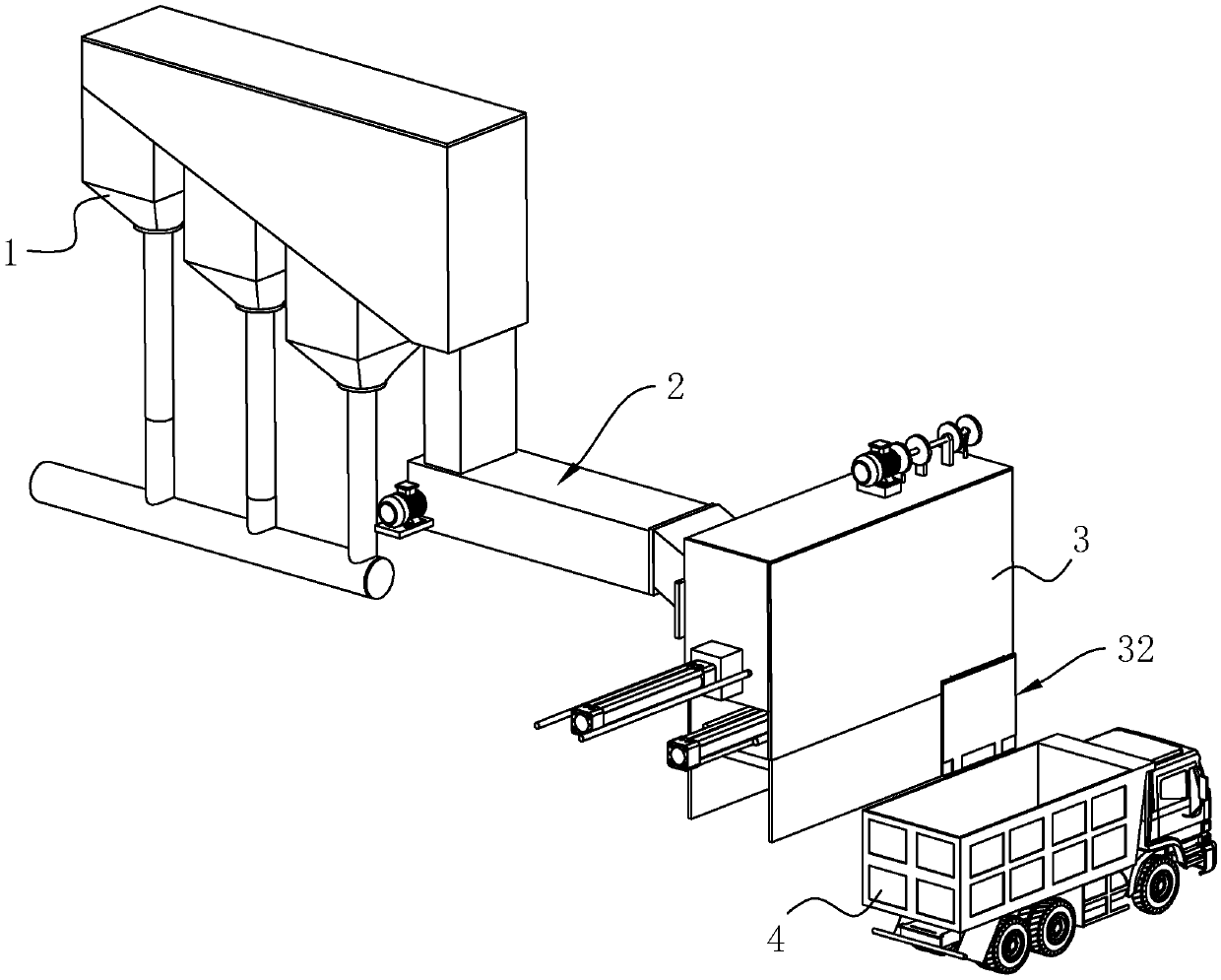
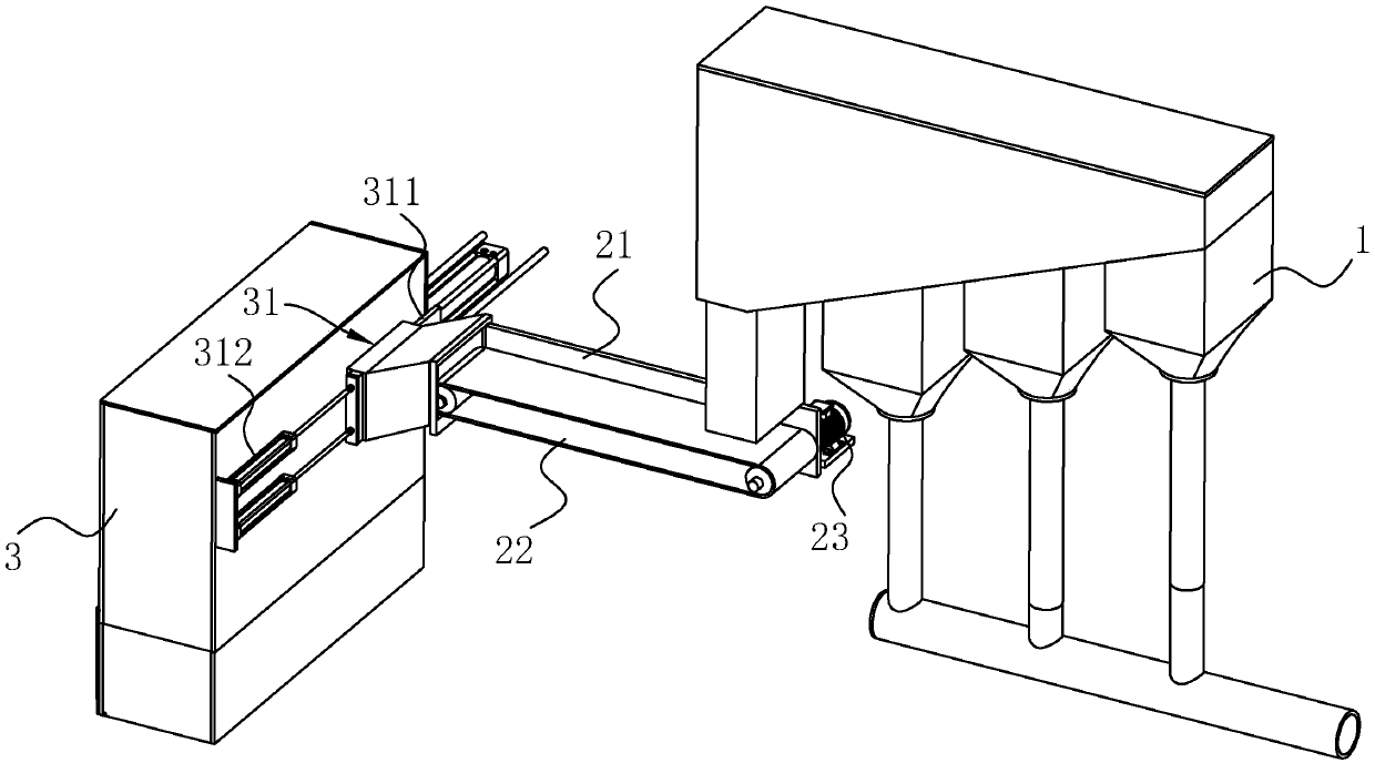
[0045] A waste residue cleaning system for waste incineration power generation, see figure 1 with figure 2 , including an incinerator 1, a conveying device 2, a slag pit 3 and a transport vehicle 4. The bottom of the incinerator 1 communicates with the end of the conveying device 2, and the end of the slag pit 3 close to the conveying device 2 is provided with a feed port 31. The feed port 31 communicates with the end of the conveying device 2 away from the incinerator 1, and the slag pit 3 is far away One side of the conveying device 2 is provided with a discharge port 32 , and the transport vehicle 4 is located below the discharge port 32 . The waste slag produced after the garbage is incinerated by the incinerator 1 enters the conveying device 2, and the conveying device 2 transports the waste slag to the slag pit 3 through the feed port 31, and the waste in the slag pit 3 finally enters the transport vehicle through the discharge port 32 4 were transported away.

[004...


PUM


Abstract

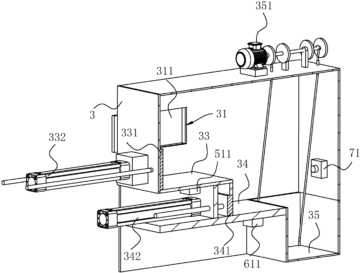
The invention discloses a waste residue cleaning system for waste incineration electricity generation and belongs to the field of waste incineration electricity generation. The key points of the technical scheme of the system include that the system comprises an incinerator, a conveying device, a residue pit and a transporting vehicle; the bottom of the incinerator communicates with the conveyingdevice; the end, away from the incinerator, of the conveying device is connected with the residue pit; the transporting vehicle can be connected with the other end of the residue pit; a first loadingplate, a second loading plate and a discharging plate are arranged in the residue pit in a stepped shape in sequence; a second push assembly used for pushing waste residue on the second loading plateto the discharging plate is connected to the second loading plate, and a second control circuit used for controlling the second push assembly is arranged on the second loading plate; and the second control circuit can be used for controlling the second push assembly to push waste on the second loading plate to the discharging plate. By means of the waste residue cleaning system provided by the invention, the problem that outward discharging of the waste residue in a residue pit is not up to standard is solved, and the temperature when the waste residue is discharged outwards can be accuratelycontrolled by arranging a temperature sensor in the residue pit.

Description

technical field [0001] The invention relates to the field of waste incineration power generation, more specifically, it relates to a waste residue cleaning system for waste incineration power generation. Background technique [0002] With the improvement of people's living standards, daily necessities have gradually increased, which has also led to an increase in domestic waste. The disposal of domestic waste is a difficult problem now. With the requirements and support of the environmental protection department, coupled with the current shortage of coal resources, using waste incineration to generate electricity is a relatively good way to solve waste. Utilizing waste-to-energy can not only reduce waste piles, eliminate the spread of bacteria and infectious diseases, reduce air pollution, but also obtain a certain amount of electricity from it. The principles of waste disposal are harmless, volume reduction, and recycling. Waste incineration power generation can save a l...

Claims


Application Information

Patent Timeline
Patent Type & Authority Applications(China)
IPC IPC(8): B65G69/20B65G47/82B65G67/04F23J1/00F23J3/00
CPCB65G47/82B65G67/04B65G69/20F23J1/00F23J3/00
Inventor 李中亚张希平
Owner 上海金山环境再生能源有限公司
Learn More