Laminating film for liquid crystal display, and liquid crystal display backlight module

A technology of liquid crystal display and lamination film, applied in the direction of instruments, optics, nonlinear optics, etc., can solve the problems of increased material loss, improved rework rate, poor scratch resistance, etc., to promote application promotion, meet scratch resistance, visual The effect of meeting the target

Pending Publication Date: 2019-04-09
CCS (SHANGHAI) FUNCTIONAL FILMS IND CO LTD
View PDF7 Cites 6 Cited by
  • Summary
  • Abstract
  • Description
  • Claims
  • Application Information

AI Technical Summary

Problems solved by technology

In order to save cost, there are two ways of enhancing the brightness: the lower enhancement is mostly used (high transparency or high fog) enhancement, and the upper enhancement is generally used to solve the interference problem with small spacing (16-25 microns) enhancement, such a small spacing enhancement when cutting It needs to be turned to different angles according to the matching with the LCD screen, generally 3-8 degrees, which not only increases the cost of materials due to the increase in material loss, but also replaces the LCD screen to verify the matching work is cumbersome, prolonging the lead-in cycle and cost; Low luminance requires the use of high-refractive index resins to increase luminance, resulting in increased costs, and low production and assembly yields due to the small-pitch structure and poor scratch resistance; Small-pitch brightening products have poor shielding performance and can be clearly seen with slight deformation; and when applied to large sizes, the stiffness of a single diaphragm is insufficient and easy to wrinkle, which is limited for large-size applications; cutting and assembling the other two diaphragms separately will cause Increased risk of poor manufacturing process, increased rework rate leading to increased loss

Method used


Image

  • Laminating film for liquid crystal display, and liquid crystal display backlight module
  • Laminating film for liquid crystal display, and liquid crystal display backlight module
  • Laminating film for liquid crystal display, and liquid crystal display backlight module

Examples


Embodiment 1

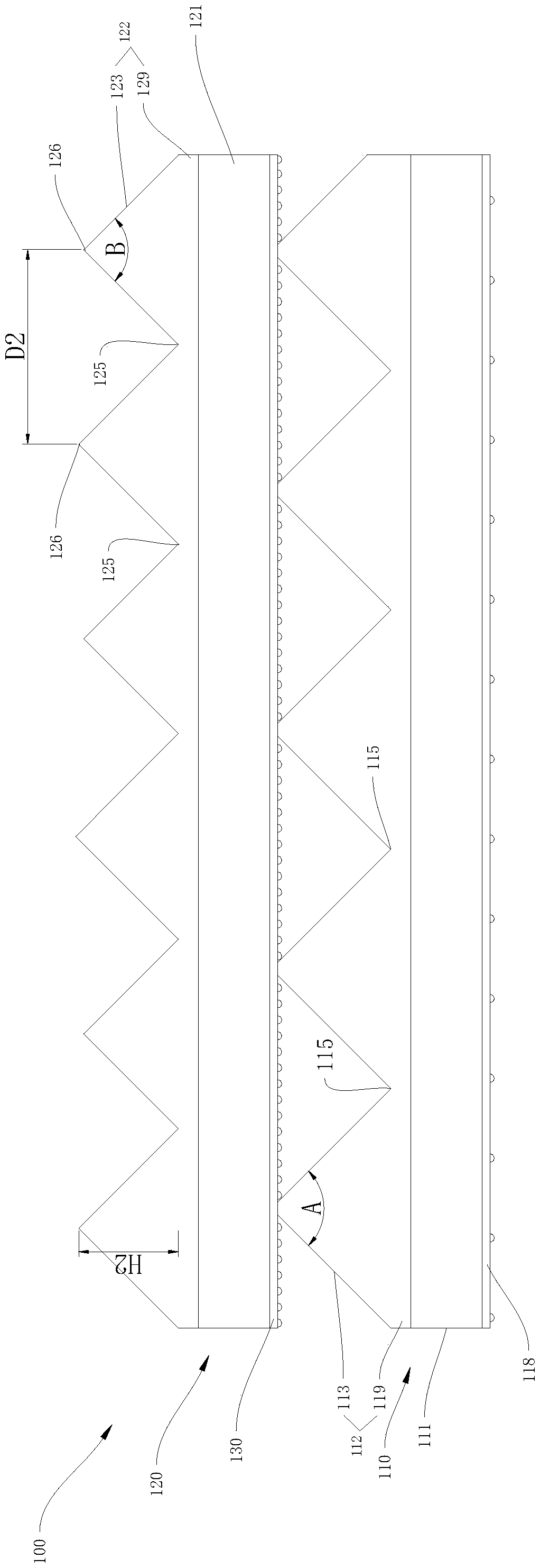
[0061] Such as figure 1 , figure 2 and image 3 As shown, the bonding film 100 for liquid crystal display includes a first structural layer film 110 and a second structural layer film 120 from bottom to top.

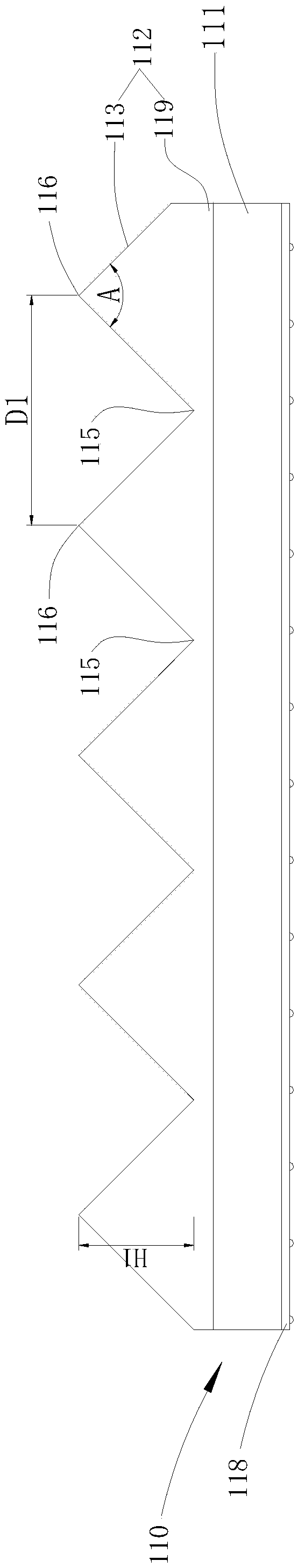
[0062] The first structural layer film 110 includes a first base film 111 and a first prism layer 112 . The first base film 111 is a 125 micron optical grade chemically treated PET film. The first prism layer 112 includes a first prism base 119 and a plurality of first prisms 113 . A plurality of first prisms 113 are arranged continuously without intervals on the first prism base 119 . The section of the first prism 113 is an isosceles triangle, and the apex angle A is a right angle. The first prism 113 has three edges, including two first bottom edges 115 and one first top edge 116 . The two first bottom ribs 115 are disposed on the first prism base 119 . The height H1 of the first top ribs 116 is 30 microns, and the distance D1 between adjacent first top ribs 1...

Embodiment 2

[0076] Such as Figure 4 , figure 2 and image 3 As shown, the bonding film 100 for liquid crystal display includes a first structural layer film 110 and a second structural layer film 120 from bottom to top.

[0077] The first structural layer film 110 includes a first base film 111 and a first prism layer 112 . The first base film 111 is a 125 micron optical grade chemically treated PET film. The first prism layer 112 is disposed on the upper surface of the first base film 111 . The first prism layer 112 includes a first prism base 119 and a plurality of first prisms 113 . A plurality of first prisms 113 are arranged continuously without intervals on the first prism base 119 . The section of the first prism 113 is an isosceles triangle, and the apex angle A is a right angle. The first prism 113 has three edges, including two first bottom edges 115 and one first top edge 116 . The two first bottom ribs 115 are disposed on the first prism base 119 . The height H1 of t...

Embodiment 3

[0091] Such as Figure 5 , figure 2 and image 3 As shown, the bonding film 100 for liquid crystal display includes a first structural layer film 110 and a second structural layer film 120 from bottom to top.

[0092] The first structural layer film 110 includes a first base film 111 and a first prism layer 112 . The first base film 111 is a 125 micron optical grade chemically treated PET film. The first prism layer 112 includes a first prism base 119 and a plurality of first prisms 113 . A plurality of first prisms 113 are arranged continuously without intervals on the first prism base 119 . The section of the first prism 113 is an isosceles triangle, and the apex angle A is a right angle. The first prism 113 has three edges, including two first bottom edges 115 and one first top edge 116 . The two first bottom ribs 115 are disposed on the first prism base 119 . The height H1 of the first apex 116 is 30 or 35 microns, and the first prisms 113 with a first apex height ...


PUM

PropertyMeasurementUnit
radiusaaaaaaaaaa
particle diameteraaaaaaaaaa

Abstract

The invention discloses a laminating film for a liquid crystal display (LCD), and a liquid crystal display backlight module. The laminating film for the LCD comprises a first structural layer film, asecond structural layer film, and a composite glue layer; the first structure layer film comprises a first base film, a first prism layer and a back coating; the first prism layer is formed by continuously arranging multiple first prisms, the first prism layer is arranged on an upper surface of the first base layer, and the back coating is arranged at a lower surface of the first base film; the structure layer film comprises a second base film and a second prism layer; the second prism layer is formed by continuously arranging multiple second prisms; the second prism layer is arranged on the upper surface of the second base film; the composite glue layer comprises PBMA or PMMA microspheres; and the first prisms are laminated on the second base film through the composite glue layer. In thepremise of ensuring that the brightness can achieve a liquid crystal display product requirement, the masking can achieve the requirement, thereby ensuring that the interference and the glare are avoided, and the visual effect reaches the standard.

Description

technical field [0001] The invention relates to a bonding film for a liquid crystal display and a backlight module of a liquid crystal display. Background technique [0002] With the popularization of TFT-LCD liquid crystal display technology, the demand for its backlight module and related optical films is also increasing. The previously adopted 4-diaphragm structure of lower diffusion, 90-degree brightening, 0-degree brightening, and upper diffusion is gradually replaced by three or even two diaphragms. With the increasing size of liquid crystals, higher requirements for stiffness, continuous thinning of products, and increasingly simplified assembly requirements for film assembly in assembly lines, DOP (increasing brightness + diffusion) laminating films and POP (increasing brightness) also appeared on the market. + lightening) laminating film, but the low brightness of DOP in the existing technology is not suitable for the use of many high-resolution LCD screens, result...

Claims


Application Information

Patent Timeline
Patent Type & Authority Applications(China)
IPC IPC(8): G02F1/13357
CPCG02F1/1336
Inventor 王清潘家鑫张宪锋许世峰孙亮刁全利胡祥发
Owner CCS (SHANGHAI) FUNCTIONAL FILMS IND CO LTD
Why Eureka
Try Eureka