A method for estimating the junction temperature of a power element IGBT in a motor controller

A technology for motor controllers and power components, which is used in thermometers, single semiconductor device testing, instruments, etc. which are directly sensitive to heat electrical/magnetic components. The relationship is not clear and other problems, to achieve the effect of improving the maximum output capability and safety, reducing the cost of components, and simplifying the junction temperature estimation

Active Publication Date: 2019-04-09
SHANGHAI DAJUN TECH
View PDF5 Cites 23 Cited by
  • Summary
  • Abstract
  • Description
  • Claims
  • Application Information

AI Technical Summary

Problems solved by technology

[0002]The junction temperature is an important condition for judging the safe operation of the power component IGBT, and the working junction temperature of the IGBT limits the maximum output capability of the motor controller
In actual use, many factors can cause IGBT overheating damage, such as design factors, complex working conditions, high vibration, temperature shock, silicone grease aging, etc.
The thermistor is usually used for indirect protection of the IGBT junction temperature. Since the thermistor is placed on the substrate or radiator of the IGBT, the temperature of the substrate or radiator is directly measured, but there is a temperature difference between the junction temperature of the IGBT and the temperature of the substrate or radi

Method used


Image

  • A method for estimating the junction temperature of a power element IGBT in a motor controller
  • A method for estimating the junction temperature of a power element IGBT in a motor controller
  • A method for estimating the junction temperature of a power element IGBT in a motor controller

Examples


Embodiment Construction

[0043]The method for estimating the junction temperature of the power element IGBT in the motor controller of the present invention comprises the following steps:

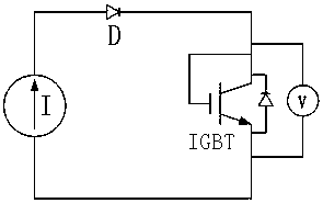
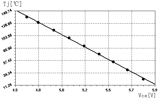
[0044] Step 1, such as figure 1 with figure 2 shown, the IGBT junction temperature T j with saturation voltage drop V ce The relationship curve is extracted, the current source I provides the IGBT current through the diode D, the base of the IGBT is shorted to the collector, and the saturation voltage drop V of the IGBT is measured by the voltage measurement device V ce , the IGBT is placed in the temperature control box, the IGBT is heated by adjusting the temperature of the temperature control box, and the corresponding saturation voltage drop V at different temperatures is recorded ce , fitted to a straight line:

[0045] T j =k×V ce +b (1)

[0046] Among them, k and b are the slope and intercept of the straight line, respectively;

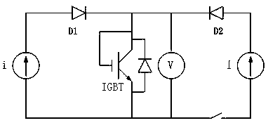
[0047] Step two, such as image 3 with Figure 4 As shown, the extra...


PUM


Abstract

The invention discloses a method for estimating the junction temperature of a power element IGBT in a motor controller. The method comprises the following steps: within a certain temperature range, the saturation voltage drop and the junction temperature of the IGBT have a relationship which can be approximately considered to be linear; the junction temperature is indirectly obtained by utilizingthe relationship between the saturated pressure drop and the temperature; Therefore, a transient thermal impedance curve from the IGBT substrate to the IGBT chip is obtained according to the corresponding relation between the junction temperature and the temperature measured by the thermistor, then an IGBT transient thermal impedance mathematical model is obtained through curve fitting, and the transient junction temperature of the IGBT is calculated through the model. According to the method, the defect of traditional IGBT junction temperature estimation is overcome, the transient thermal resistance model of the IGBT is established according to actual test data, the precision of model parameters is improved, the junction temperature estimation is simple, the implementation is convenient,the calculated amount is small, the component cost is reduced, the estimation error is small, and the maximum output capability and safety of the motor controller are improved.

Description

technical field [0001] The invention relates to the technical field of motor control, in particular to a method for estimating the IGBT junction temperature of a power element in a motor controller. Background technique [0002] The junction temperature is an important condition for judging the safe operation of the power component IGBT, and the working junction temperature of the IGBT limits the maximum output capability of the motor controller. In actual use, many factors can lead to IGBT overheating damage, such as design factors, complex working conditions, high vibration, temperature shock, silicone grease aging, etc. The thermistor is usually used for indirect protection of the IGBT junction temperature. Since the thermistor is placed on the substrate or radiator of the IGBT, the temperature of the substrate or radiator is directly measured, but there is a temperature difference between the junction temperature of the IGBT and the temperature of the substrate or radiat...

Claims


Application Information

Patent Timeline
IPC IPC(8): G06F17/17G01N25/20G01R31/26G01K7/22
CPCG06F17/17G01K7/22G01N25/20G01R31/2601
Inventor 陈双王双全黄洪剑
Owner SHANGHAI DAJUN TECH
Why Eureka
Try Eureka