Distribution transformer region sensing terminal device and method

A technology for terminal devices and station areas, applied in circuit devices, electrical components, sustainable buildings, etc., can solve the problems of poor application effect of detection algorithms, excessive equipment itself, incomplete detection technology, etc. Quick release, compact structure, and easy on-site application

CN109599941AInactive Publication Date: 2019-04-09JIANGSU INTELEVER ENERGY TECH CO LTD
4 Cites 2 Cited by

Patent Information

Authority / Receiving Office
CN · China
Patent Type
Applications(China)
Current Assignee / Owner
Publication Date
2019-04-09
Estimated Expiration
Not applicable · inactive patent

Smart Images

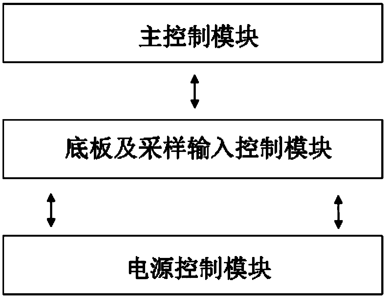
  • Figure 1
    Figure 1
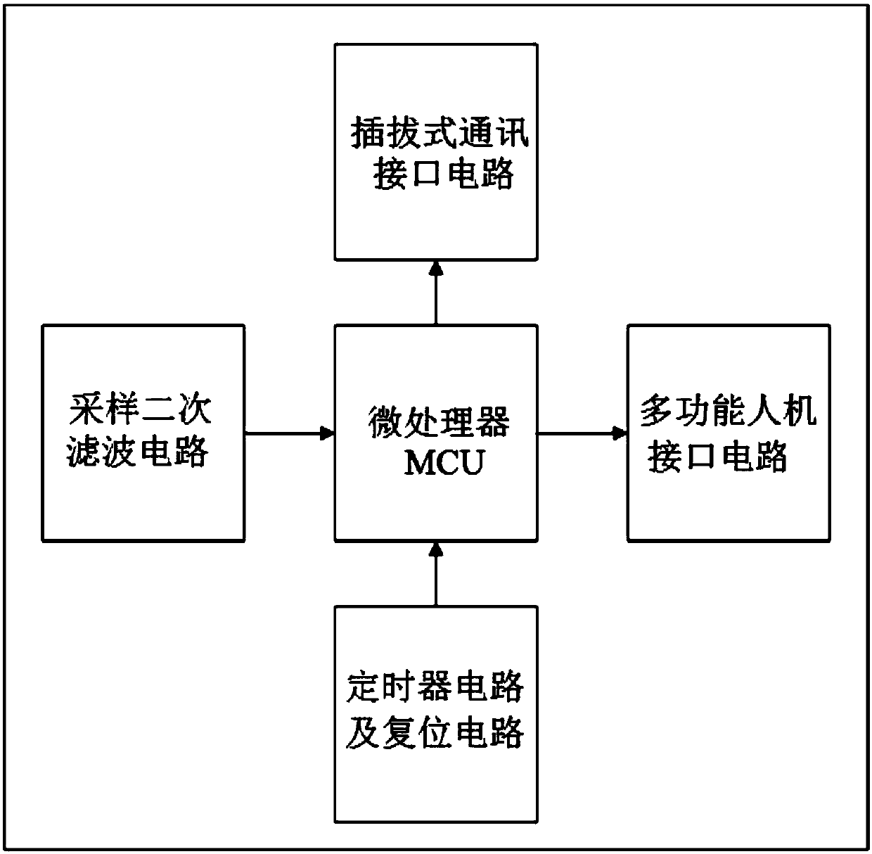
  • Figure 2
    Figure 2
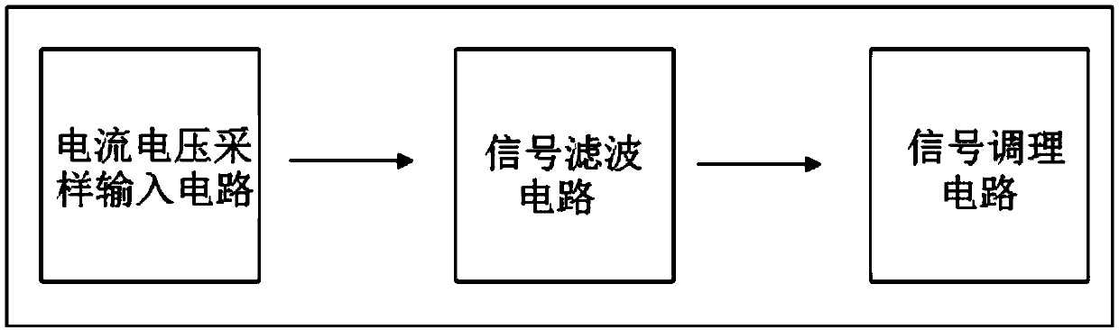
  • Figure 3
    Figure 3
Patent Text Reader

Abstract

The invention discloses a distribution transformer region sensing terminal device and method. The device comprises a main control module, a sampling input control module and a power control module; the main control module realizes data analysis and processing and sends a processing result through a communication interface; the sampling input control module is connected with the main control moduleby adopting a plug pin, the input of each of a sampling signal and a power signal to the main control module can be realized through the plug pin, the sampling input control module is connected withthe power control module through the plug pin, and a power supply source thereof is from the power control module; the power control module realizes the input conversion of an AC power and realizes the standby power function. The method comprises the steps of real-time monitoring a voltage current signal, conditioning the filter, judging whether the data is effective, analyzing the data and outputting the data. The region sensing terminal function can be realized through three function boards, and the region full-state monitoring and diagnosis, the region topology automatic identification, thepower outage active reporting technology and like power-utilization advanced measurement functions are realized.
Need to check novelty before this filing date? Find Prior Art

Description

technical field

[0001] The invention relates to a sensing terminal device and method for a distribution transformer area, and belongs to the technical field of smart grid and smart electricity utilization. Background technique

[0002] With the construction of a strong and smart grid, the reliability of my country's power grid has been continuously improved, and the grid company's own assessment requirements for power supply services have also increased year by year. my country's residential electricity consumption is growing extremely fast, and the residential user station area presents problems such as a large number of users, complex individual electricity consumption behaviors, difficult fault location, and low level of grid status monitoring.

[0003] At present, the level of active perception of faults in residential areas is low, and troubleshooting takes a long time. The technical level of power outage troubleshooting in residential areas is still in the passive repa...

Examples

Embodiment Construction

[0044] The present invention will be further explained below in conjunction with the accompanying drawings and specific embodiments. It should be understood that the following specific embodiments are only used to illustrate the present invention but not to limit the scope of the present invention.

[0045] figure 1 It is a structural block diagram of the present invention. It can be seen from the accompanying drawings that the sensing terminal device in the distribution transformer station area includes: a main control module, a sampling input control module, and a power supply control module. The terminal adopts a three-layer structure as a whole, and each module is arranged in a stacked manner. On the top of the terminal is the main control module, which implements data analysis and processing, and sends the processing results through the communication interface, which is connected to the sampling input control module through pins; in the middle layer is the sampling input...