
Control method of full-bridge rectifier and full-bridge rectifying circuit

A technology of a full-bridge rectifier circuit and control method, which is applied in the direction of converting AC power input to DC power output, electrical components, and output power conversion devices, etc., can solve problems that greatly affect the working reliability of full-bridge rectifier circuits.

Active Publication Date: 2019-04-09
MAXIC TECHNOLOGY CORPORATION
View PDF5 Cites 5 Cited by
  • Summary
  • Abstract
  • Description
  • Claims
  • Application Information

AI Technical Summary

Problems solved by technology

[0013] In view of this, the purpose of this application is to provide a control method for full-bridge rectification and a full-bridge rectifier circuit, which is used to solve the problem of the large impact of noise on the resolution of the comparator in the prior art, which makes the work reliability of the full-bridge rectifier circuit lower question

Method used


Image

  • Control method of full-bridge rectifier and full-bridge rectifying circuit
  • Control method of full-bridge rectifier and full-bridge rectifying circuit
  • Control method of full-bridge rectifier and full-bridge rectifying circuit

Examples


Embodiment Construction

[0069] In order to make the purpose, technical solutions and advantages of the embodiments of the present application clearer, the technical solutions in the embodiments of the present application will be clearly and completely described below in conjunction with the drawings in the embodiments of the present application. Obviously, the described embodiments are only It is a part of the embodiments of this application, not all of them. The components of the embodiments of the application generally described and illustrated in the figures herein may be arranged and designed in a variety of different configurations. Accordingly, the following detailed description of the embodiments of the application provided in the accompanying drawings is not intended to limit the scope of the claimed application, but merely represents selected embodiments of the application. Based on the embodiments of the present application, all other embodiments obtained by those skilled in the art without...


PUM


Abstract

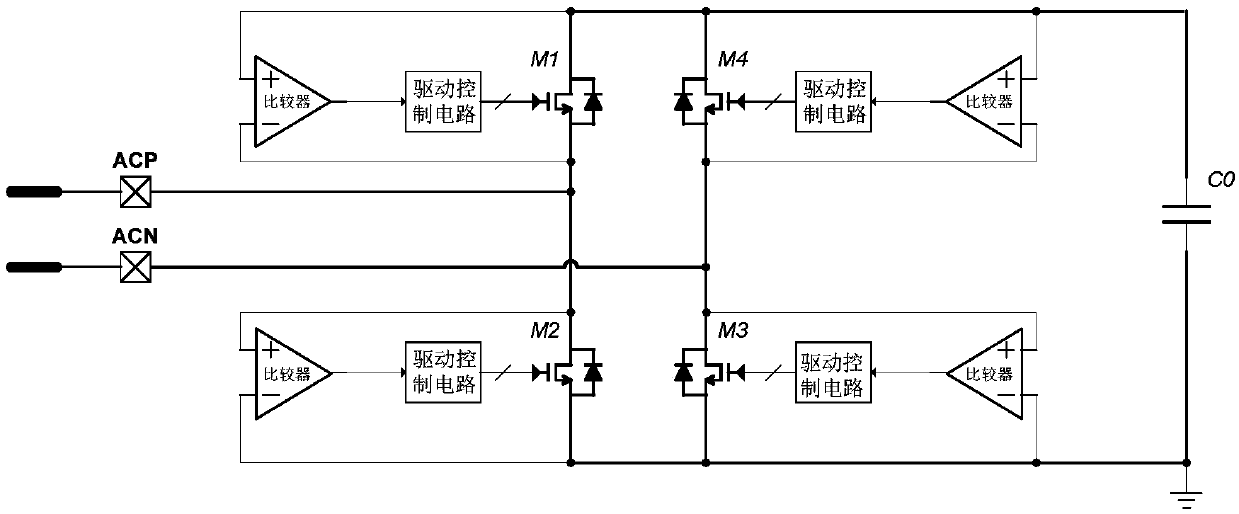
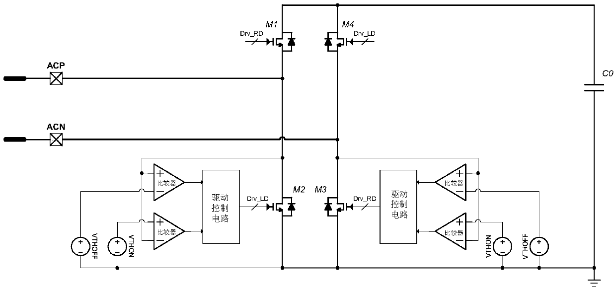
The invention provides a control method of a full-bridge rectifier and a full-bridge rectifying circuit. The method comprises the following steps: in the current period of input current, detecting thefirst voltage of the drain electrode of a half-bridge metal oxide semiconductor field-effect transistor MOSFET of the full-bridge rectifying circuit, determining the first voltage to be greater thana preset turn-off voltage threshold value, and turning off the half-bridge MOSFET; after the half-bridge MOSFET is turned off, detecting the second voltage of the drain electrode of the half-bridge MOSFET; if the second voltage is detected to be smaller than or equal to a preset turn-off voltage comparison threshold value, delaying preset time slices on the basis of the conduction time of a drivecontrol signal for controlling the gate electrode of the half-bridge MOSFET in the next period, if the second voltage is not detected to be smaller than or equal to the preset turn-off voltage comparison threshold value, reducing the preset time slices on the basis of the conduction time of the drive control signal for controlling the gate electrode of the half-bridge MOSFET in the next period. The operational reliability of the full-bridge rectifying circuit can be promoted.

Description

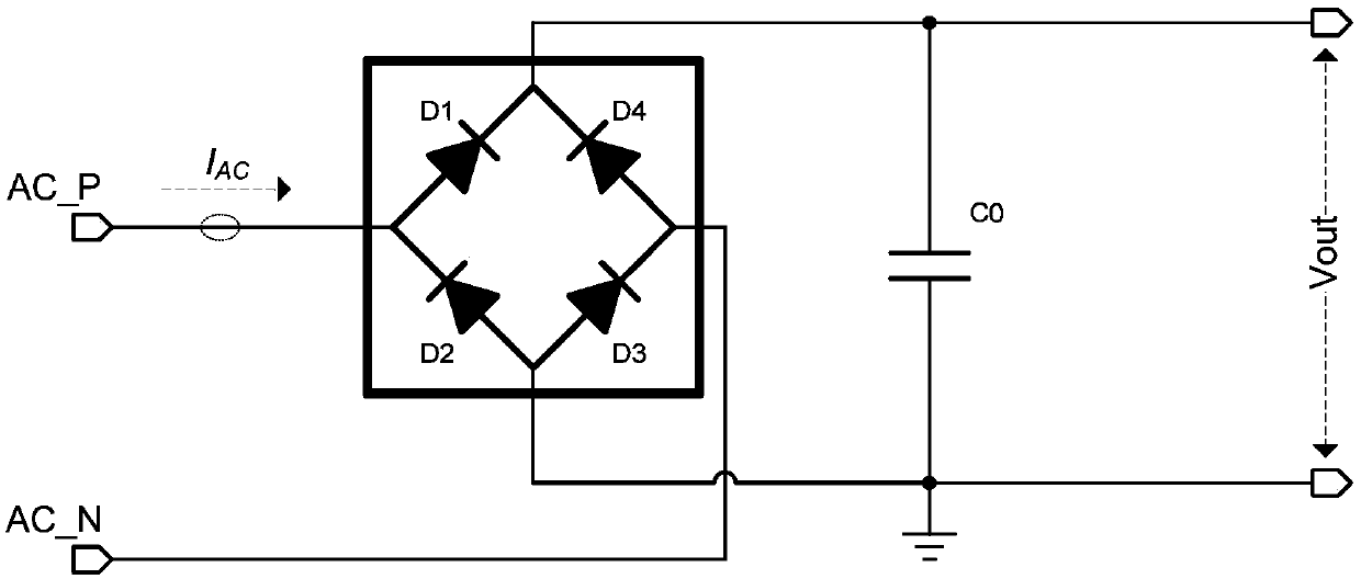
technical field [0001] The present application relates to the technical field of rectification, and in particular, to a control method of full-bridge rectification and a full-bridge rectification circuit. Background technique [0002] The full-bridge rectifier circuit is a commonly used rectifier circuit in power management, which is used to convert the input AC voltage into DC voltage. figure 1 It is a schematic structural diagram of a full-bridge rectifier circuit in the prior art. Such as figure 1 As shown, when the AC input current (I AC ) is positive, the first diode (D1) and the third diode (D3) are turned on, charging the output capacitor (C0) and outputting a DC voltage (Vout); when the input AC current (I AC ) is negative, the second diode (D2) and the fourth diode (D4) are turned on to charge the output capacitor (C0) and output a DC voltage (Vout). [0003] In practical applications, since the diode has a certain turn-on voltage threshold, when a large current...

Claims


Application Information

Patent Timeline
IPC IPC(8): H02M7/219
CPCH02M7/219
Inventor 郭越勇
Owner MAXIC TECHNOLOGY CORPORATION
Learn More