[0033] In order to make the objectives, technical solutions and advantages of the present invention clearer, the present invention will be further described in detail below with reference to the accompanying drawings. Merely to declare that the terms up, down, left, right, front, back, inside, and outside that appear or will appear in the text of the present invention are only based on the drawings of the present invention, and they are not specific to the present invention. limited.
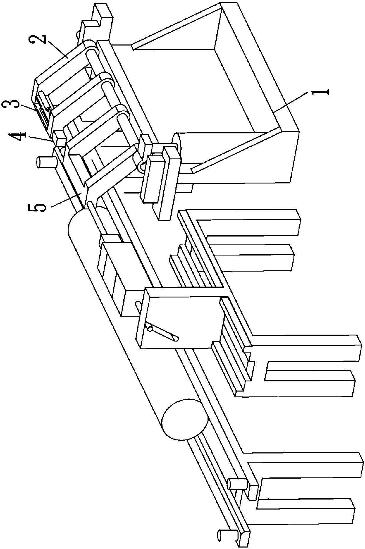
[0034] See figure 1 , The present invention discloses a fixed-length sawing and coding machine for aluminum rods, which is arranged above the aluminum rod transportation line and includes a frame 1, a swing arm component installed on the frame 1, 2, and a swing arm mounted on the pendulum. The support arm 3 on the arm part 2 and the sawing part 4 and the coding assembly 5 fixed on the support arm 3. The swing member drives the support arm 3, the sawing part 4 and the coding assembly 5 installed on the support arm 3 to lift or press down, transport the aluminum rod when lifting, and saw and beat the aluminum rod when pressing down. So as to prevent interference between the sawing, coding and transportation actions of the aluminum rod; the sawing part 4 completes the fixed-length and sawing of the aluminum rod; the coding component performs marking on the end of the aluminum rod code. The aluminum rod can be sawed and coded at the same time to improve the production efficiency and cutting quality of the aluminum rod. The specific structure of each component will be described below.
[0035] See figure 2 The sawing part 4 includes a fixed-length component 6, a pressing component 7, a sawing component 8 and a cooling component 9 arranged at the end of the fixed-length component 6, and the fixed-length component 6 calibrates the length to be sawed The pressing assembly 7 presses the aluminum rod during sawing, and the cooling assembly 9 provides cooling liquid during sawing to avoid aluminum sticking. Specifically, the fixed-length assembly 6 calibrates the length to be sawed by moving along the axis of the aluminum rod, and can be marked according to a preset length or calculated by calculating the required length of the aluminum rod, the rotational speed of the motor, and the periodic distance of the transmission. The relationship between determines the length of the sawing. The pressing component 7 compresses the aluminum rod before the aluminum rod is sawed, so as to avoid the sliding of the aluminum rod during the sawing. The pressing assembly 7 exerts a downward force on the aluminum rod to increase the friction between the aluminum rod and the transportation line. The cooling assembly 9 is used for cooling and lubricating the saw blade, and improving the smoothness of the sawing surface.
[0036] Specifically, the fixed-length assembly 6 includes a fixing frame 61, a precision screw 62 connected to the fixing frame 61, a screw nut 63 installed on the precision screw 62, and a hinged connection with the screw nut 63 The rolling element 64; the rolling element 64 includes a pressure rod 641, a rolling element 642 provided at the end of the pressure rod 641, and an elastic support 643 connecting the pressure rod 641 and the screw nut 63 . The precision lead screw 62 is driven by a programmable motor. The precision lead screw 62 has a corresponding lead P to determine the relationship between the length L of the aluminum rod to be sawed, the lead P, and the length M occupied by the equipment, By controlling the number of rotations of the motor, the screw nut 63 is stopped at the corresponding position on the precision screw 62. The pressing rod 641 of the rolling element applies a certain pressure to the aluminum rod under the action of the spring force, which can improve the stability of the screw nut 63 during operation. At the same time, the pressing rod 641 is provided at the end There is a rolling element 642, which reduces the friction between the rolling element and the aluminum rod. With the above fixed-length assembly 6, the length of the sawing can be adjusted according to the required length, and the number of rotations of the motor can be adjusted, which is convenient and reliable.
[0037] The sawing assembly 8 includes a second screw nut 81 that cooperates with the precision screw 62, a guide rail 82 provided below the precision screw 62, and a cutter installed on the second screw nut 81 The cutting part 83 moves along the guide rail 82; the cutting part 83 includes a base 831 fixed to the second screw nut 81, a rocker 832 hinged to the base 831, and The saw blade 833 at the end of the rocker 832 and the hydraulic cylinder 834 that drives the rocker 832 to swing. Specifically, the sawing assembly 8 is installed on the precision lead screw 62 and arranged on the front side of the fixed-length assembly 6. In order to improve the safety of the sawing assembly 8, two guide rails 82 parallel to the central axis of the aluminum rod are provided under the precision screw 62, and the cutter portion 83 is installed on the second screw nut 81, and The bottom is matched with the guide rail 82. The cutter portion 83 adopts a circular sawing method, the saw blade 833 is provided with a high-speed motor 835; the rocker 832 is provided between the high-speed motor 835 and the saw blade 833, and the other of the rocker 832 One end is hinged with the base 831; the middle of the rocker 832 is connected with a hydraulic cylinder 834, which fills the back cavity of the hydraulic cylinder 834 with oil to push the piston rod out, presses the saw blade 833 below, and saws the aluminum rod. Using the above sawing method, the structure is simple and reliable; according to the softer material of the aluminum rod, a high-speed sawing method is adopted to improve the smoothness and flatness of the sawing surface of the aluminum rod.
[0038] The pressing assembly 7 is arranged on the second screw nut 81, and the pressing assembly 7 includes a bottom plate 71, an upright rod 72 arranged on the bottom plate 71, and a pressing plate arranged on the upright rod 72 73. A cushion block 74 directly below the pressing plate 73 and a pressing hydraulic cylinder 75 provided with the front end of the pressing plate 73, the cushion 74 being higher than the height of the aluminum rod; the pressing hydraulic cylinder 75 drives the The pressing plate 73 is pressed down to compress the aluminum rod. Specifically, because the height of the spacer 74 is higher than the height of the aluminum rod, the pressing hydraulic cylinder 75 is located at the front end of the pressing plate 73, and the force of the pressing hydraulic cylinder 75 on the pressing plate 73 is Converted into the force of pressing down the aluminum rod, the aluminum rod can be compressed without a complicated structure.
[0039] The structure of the sawing part 4 is described in detail above. By precisely fixing the length, simply and effectively compressing the aluminum rod, and quickly sawing the aluminum rod, the fixed-length sawing of the aluminum rod can be realized, with a simple structure and easy operation.
[0040] See image 3 Furthermore, since aluminum sticking is prone to occur due to high temperature during sawing of aluminum rods, in order to solve this problem, the sawing part 4 is further provided with a cooling assembly 9. The cooling assembly 9 is arranged on the base 831. The cooling assembly 9 includes a liquid storage tank 91, a connecting pipe 92, a cooling liquid nozzle 93, and a recovery tank 94. The recovery tank 94 is arranged on the transportation line. Below, the upper part of the recovery tank 94 is provided with a filter 95. The cooling liquid in the liquid storage tank 91 flows through the connecting pipe 92 to the cooling liquid nozzle 93. The nozzle of the cooling liquid nozzle 93 faces the saw blade 833. When the aluminum rod is sawed, the cooling liquid is continuously sprayed to the saw blade 833. After cooling the saw blade 833, it flows into the recovery tank 94 provided below the transportation line. The surface of the recovery tank 94 is provided with a filter 95, which is used to filter the aluminum chips generated by sawing. To further recover the coolant.
[0041] See Figure 4 Further, the edge of the sawed aluminum rod is prone to burrs, which affects further packing and transportation procedures. To eliminate burrs, the sawing portion 4 is also provided with a deburring component 10. The deburring assembly 10 includes a motor 101, a gear 102 mounted on the output shaft of the motor 101, and a rack 103 meshing with the gear 102. The end of the rack 103 is provided with a file 104; the file 104 is tapered Round tube shape with rough friction surface on the inner wall. Specifically, the motor 101 is installed on the base 831 of the sawing part 4, and the motor 101 drives the gear 102 to rotate to drive the rack 103 to move to drive the file 104 to move back and forth to remove burrs. Wherein, the file 104 is in the shape of a tapered tube, the diameter of the cone increases in the direction of friction, and the smallest diameter is slightly larger than the diameter of the aluminum rod, so as to smoothly eliminate the burrs at the outer diameter of the aluminum rod.
[0042] After the pressing component 7 compresses the aluminum rod, the coding component 5 performs coding on the aluminum rod at this time, which can realize sawing and coding at the same time and improve efficiency.
[0043] See Figure 5 The coding assembly 5 includes a character code body 51 and a power cylinder 52 connected to the character code body 51. The power cylinder 52 drives the character code body 51 to impact an aluminum rod to complete the coding.
[0044] The coding assembly 5 further includes a bracket 53 which is fixed to the support arm 3, the bracket 53 is provided with the power cylinder 52, and the end of the power cylinder 52 is connected to a code body 51 , The bracket 53 is also provided with a buffer cylinder 54, the end of the buffer cylinder 54 is connected with a certain long head 55, the ejection direction of the power cylinder 52 and the buffer cylinder 54 and the movement direction of the aluminum rod relatively. Specifically, when the aluminum rod that needs to be coded rushes toward the coding assembly 5 at high speed along the transportation line, the buffer cylinder 54 is slowly retracted to the final position under the pressure of the coding assembly 5, and then slowly Extend forward to fix the end of the aluminum rod and provide a reference for the length fixing process; the fixed length head 55 is provided with the character code body 51 inside, and the character code body 51 is connected to the power cylinder 52, so The power cylinder 52 extends and pushes the code body 51 to extend, and hits the aluminum rod to be coded to complete the code.
[0045] The swing arm component 2 includes a driving component 21 and a rotating component 22. The driving component 21 drives the support arm 3 component to turn over and lifts the sawing portion 4 and the coding component 5 for transportation of the sawed, Aluminum rod after coding.
[0046] Specifically, the driving assembly 21 includes a swing arm cylinder 211, the rotation assembly 22 includes a guide sleeve 221 and a guide post 222 sleeved with the guide sleeve 221, and the guide post 222 is detachable from the support arm 3 connection. Before sawing and coding, the swing arm cylinder 211 of the swing arm component 2 is in the ejected state, and does not interfere with the movement of the aluminum rod. When sawing and coding are required, the swing arm cylinder 211 retracts to reduce The sawing part 4 and the coding assembly 5 are placed horizontally and maintain the above state to complete the actions of fixing the length, sawing and coding. After the coding is completed, the swing cylinder is contracted and the guide post 222 is driven to rotate, so that the coding assembly 5, the support arm 3 and the sawing part 4 are lifted as a whole, and are separated from the production line by at least one aluminum ingot diameter. The cut aluminum ingot is transported to the next process location through the production line.
[0047] In addition, the frame 1 includes an upper platform 11 and a support body 12 supporting the upper platform 11; the bottom of the support body 12 is provided with pulleys 13, and the upper platform 11 is provided with multiple rollers (not shown in the figure) Shown), the rollers (not shown in the drawings) roll along the upper plane of the transportation line, so that the frame 1 moves smoothly.
[0048] In summary, the aluminum rod is placed on the transportation line for transportation, and when it reaches the predetermined sawing position area, the aluminum rod stops moving; the swing arm member 2 drives the support arm 3 to press down, so that the The support arm 3 is horizontal, and the sawing part 4 and the coding assembly 5 connected to the support arm 3 are then flat; the transportation line drives the aluminum rod to continue to move until the aluminum rod and the coding assembly 5 After the fixed-length head 55 of the contact, stop to determine the position of the end surface; the sawing part 4 moves to complete the length-fixing, pressing and sawing actions in sequence, and at the same time, the coding assembly 5 impacts the end surface of the aluminum rod, The coding is completed; after that, the swing arm component 2 is lifted, driving the support arm 3 to lift, so that the sawing part 4 and the coding assembly 5 do not affect the transportation of the aluminum rod. The aluminum rod can be sawed and coded at the same time to improve the production efficiency and cutting quality of the aluminum rod.
[0049] The above are the preferred embodiments of the present invention. It should be pointed out that for those of ordinary skill in the art, without departing from the principle of the present invention, several improvements and modifications can be made, and these improvements and modifications are also considered This is the protection scope of the present invention.