
Take-up and pay-off buffering structure for mooring unmanned aerial vehicle and working method thereof

A cushioning structure and cable take-up technology, which is applied in the direction of conveying filamentous materials, thin material handling, transportation and packaging, etc. The effect of cable accumulation and cable arrangement is even

Pending Publication Date: 2019-04-12
SHENZHEN SUNWIN INTELLIGENT CO LTD
View PDF10 Cites 8 Cited by
  • Summary
  • Abstract
  • Description
  • Claims
  • Application Information

AI Technical Summary

Problems solved by technology

However, the existing automatic take-up and pay-off equipment generally has local defects. The fully automatic take-up and pay-off uses the motor to drive the reel to rotate in reverse to realize the functions of take-up and pay-off, because the reel rotates at a medium-high speed during work. There is inertia at the moment of stopping, and the winding at the moment of stopping usually continues to rotate for a period of time and then stops. At this time, the cable will be entangled or knotted on the winding drum. The actual drone is frequently affected by the wind speed on the cable during the ascent process. If there is a momentary stop, the longer the time, the wiring of the entire winding drum will be disordered, which will seriously affect the flight safety of the drone, and even cause the take-up and release system to be paralyzed and unusable

Method used


Image

  • Take-up and pay-off buffering structure for mooring unmanned aerial vehicle and working method thereof
  • Take-up and pay-off buffering structure for mooring unmanned aerial vehicle and working method thereof
  • Take-up and pay-off buffering structure for mooring unmanned aerial vehicle and working method thereof

Examples


Embodiment Construction

[0028] The following will clearly and completely describe the technical solutions in the embodiments of the present invention with reference to the accompanying drawings in the embodiments of the present invention. Obviously, the described embodiments are some of the embodiments of the present invention, but not all of them. Based on the embodiments of the present invention, all other embodiments obtained by persons of ordinary skill in the art without making creative efforts belong to the protection scope of the present invention.

[0029] It should be understood that when used in this specification and the appended claims, the terms "comprising" and "comprises" indicate the presence of described features, integers, steps, operations, elements and / or components, but do not exclude one or Presence or addition of multiple other features, integers, steps, operations, elements, components and / or collections thereof.

[0030] It should also be understood that the terminology used ...


PUM


Abstract

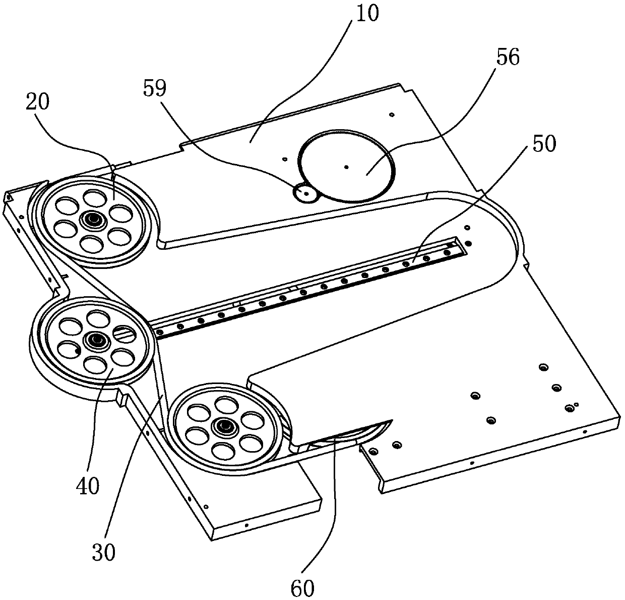
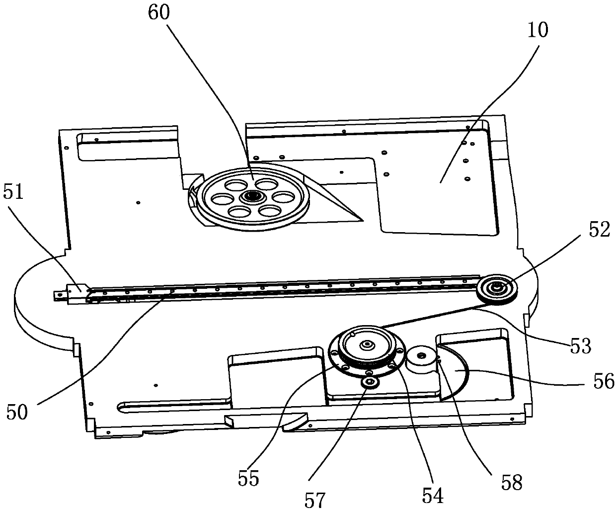
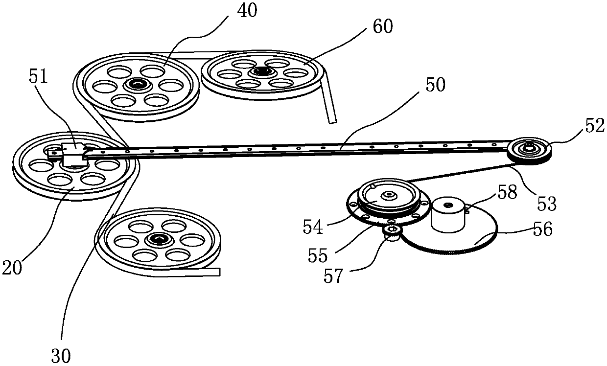
The invention relates to a take-up and pay-off buffering structure for a mooring unmanned aerial vehicle and a working method thereof. The structure comprises a take-up and pay-off wheel, a bufferingassembly and an adjusting assembly. The buffering assembly comprises a buffering wheel, a sliding rail, a sliding block and an adjusting assembly. A distance for a cable to pass through is formed between the take-up and pay-off wheel and the buffering wheel. The adjusting assembly comprises a position adjusting structure, a winding control mechanism used for controlling the take-up and pay-off speed of a winding cylinder, and a sensor used for detecting the position of the buffering wheel. The sliding block is connected with the buffering wheel and located on the sliding rail. The position adjusting structure is connected with the sliding block. The sensor and the position adjusting structure are connected with the winding control structure. The sensor detects the position of the bufferingwheel, a detection signal is transmitted to the winding control structure, and the winding control structure controls the winding cylinder to take up and pay off wires and controls the take-up and pay-off speed of the winding cylinder. According to the structure, in the ascending pay-off process or the descending take-up process, the phenomenon of winding or knotting is avoided, and winding displacement of the whole winding cylinder is uniform.

Description

technical field [0001] The invention relates to an unmanned aerial vehicle retractable wire structure, more specifically, a tethered unmanned aerial vehicle retractable wire buffer structure and its working method. Background technique [0002] Unmanned aircraft, referred to as "UAV", is an unmanned aircraft controlled by radio remote control equipment and its own program control device. There is no cockpit on board, but equipment such as autopilot and program control device are installed. The development of the tethered UAV has solved the problem of the limited flight time of the UAV. As the core of the tethered UAV, the tethered rope power system is extremely important. [0003] Tethered drones have been widely used in the industry, and the fully automatic tethered take-up and release device has also appeared. However, the existing automatic take-up and pay-off equipment generally has local defects. The fully automatic take-up and pay-off uses the motor to drive the reel...

Claims


Application Information

Patent Timeline
Patent Type & Authority Applications(China)
IPC IPC(8): B65H75/38B65H75/44B65H51/22
CPCB65H51/22B65H75/38B65H75/44B65H2701/35
Inventor 毛方海王秋阳杨学武黄桃丽孙桂祥陈欣宇
Owner SHENZHEN SUNWIN INTELLIGENT CO LTD
Learn More