
Method for concrete pouring in arch bridge steel pipe, device and application thereof

A technology for concrete and concrete delivery pumps, applied in arch bridges, bridges, buildings, etc., can solve the problems of unguaranteed concrete compactness and low operating efficiency, and achieve the effect of unguaranteed concrete compactness, low manufacturing cost and simple structure

Inactive Publication Date: 2019-04-12
CHINA MCC5 GROUP CORP
View PDF5 Cites 0 Cited by
  • Summary
  • Abstract
  • Description
  • Claims
  • Application Information

AI Technical Summary

Problems solved by technology

[0004] The technical problem to be solved by the present invention is to provide a concrete pouring method and its device and application in the steel pipe of the arch bridge. The quality requirements of the existing technology solve the problems that the concrete compactness cannot be guaranteed and the operation efficiency is low.

Method used


Image

  • Method for concrete pouring in arch bridge steel pipe, device and application thereof
  • Method for concrete pouring in arch bridge steel pipe, device and application thereof
  • Method for concrete pouring in arch bridge steel pipe, device and application thereof

Examples


Embodiment 1

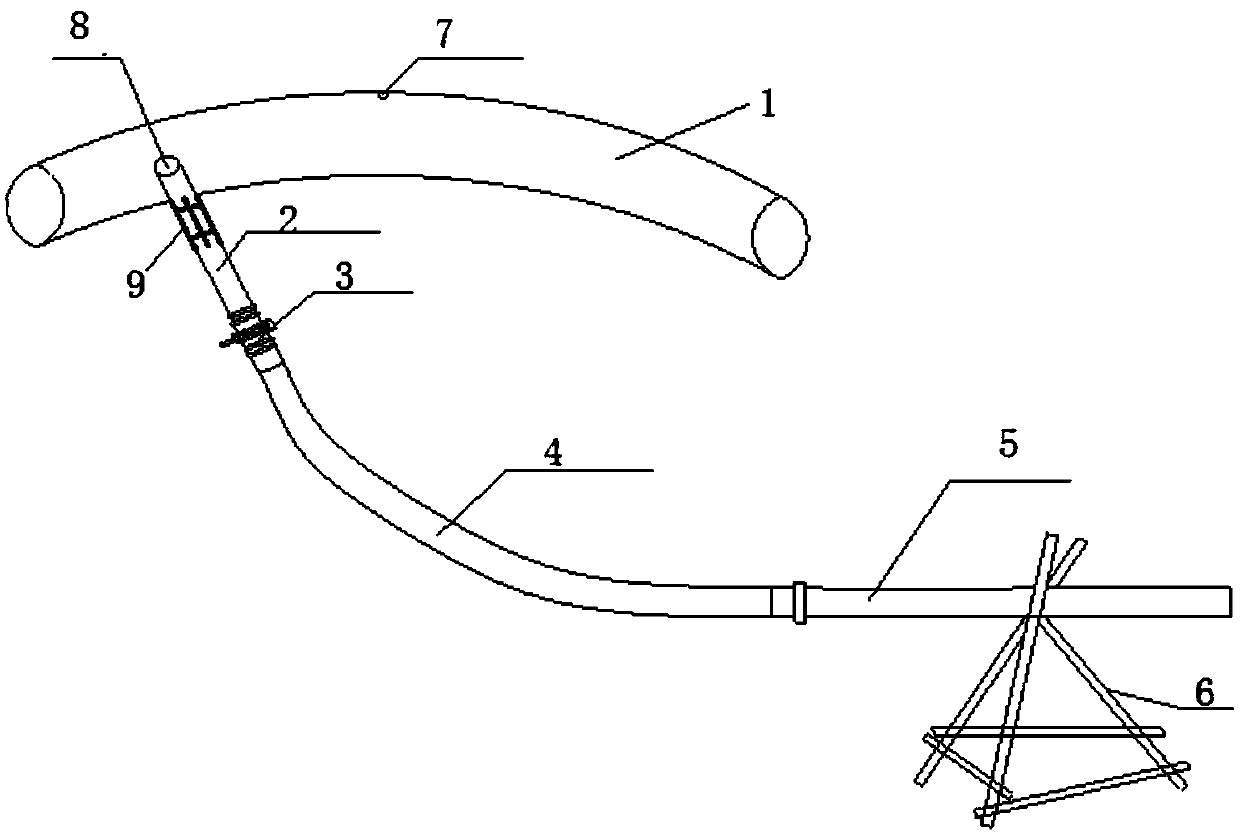
[0041] This embodiment discloses a concrete pouring device in a steel pipe for an arch bridge, including:

[0042] Steel pipe 1, the two ends of the steel pipe 1 are fixed on the bridge foundation, and the top surface of the steel pipe 1 is provided with an overflow hole 7;

[0043] A feeding pipe 2, the upper end of the feeding pipe 2 is half embedded in the end of the steel pipe 1;

[0044] A stop structure 3, located at the lower end of the feed pipe 2;

[0045] A high-pressure pipe 4 is connected to the flow-stopping structure 3;

[0046] A pump pipe 5, one end of the pump pipe 5 is connected to the high-pressure pipe 4, and the other end is connected to the concrete delivery pump;

[0047] A stabilizing bracket 6, located below the pump tube 5;

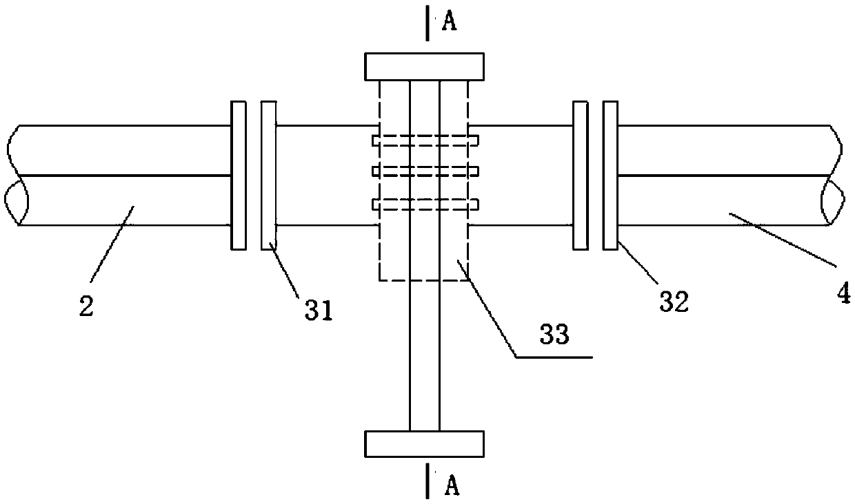
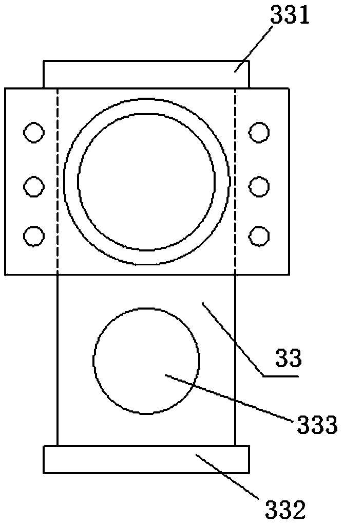
[0048] Wherein, the stop structure 3 includes a front joint 31 and a rear joint 32, the front joint 31 is connected to the feed pipe 2, and the rear joint 32 is connected to the high-pressure pipe 4;

[0049] The front joint ...

Embodiment 2

[0058] This embodiment discloses a method for pouring concrete in a steel pipe using the concrete pouring device in a steel pipe for an arch bridge disclosed in Embodiment 1, including the following steps:

[0059] S1: Concrete is transported after the concrete pouring device in the steel pipe is built;

[0060] S2: Stop pumping after the concrete in the steel pipe overflows, and close the flow-stopping structure;

[0061] S3: cleaning the remaining concrete on the steel pipe;

[0062]S4: After the final setting of the concrete, remove the flow-stop structure, cut off the feed pipe, repair the cut of the feed pipe and the overflow hole.

[0063] The concrete steps of described S2 are:

[0064] S21: after the pouring of the concrete delivery pump, control the pump pressure for 2-3 minutes;

[0065] S22: Remove the high-pressure pipe after the movable valve plate closes the channel of the feed pipe.


PUM


Abstract

The invention relates to the field of civil engineering, and in particular to a method for concrete pouring in an arch bridge steel pipe, a device and application thereof. The device for concrete pouring in the arch bridge steel pipe comprises a steel pipe, a feeding pipe, a flow stop structure, a high pressure pipe, a pump pipe and a stabilizing bracket, wherein a top surface of the steel pipe isprovided with an overflow hole; the flow stop structure is located at a lower end of the feeding pipe; the high pressure pipe is connected with the flow stop structure; one end of the pump pipe is connected with the high pressure pipe, and the other end of the pump pipe is connected with a concrete delivery pump; the stabilizing bracket is located below the pump pipe. The device for the concretepouring in the arch bridge steel pipe disclosed by the invention is simple in structure and low in manufacturing cost; the method for concrete pouring in the steel pipe by using the pouring device issimple in steps and easy to operate; with the device and the method disclosed by the invention, the one-time pouring of the concrete can be implemented, the high compactness of concrete pouring can beachieved, the quality requirements of concrete pouring in the pipe are guaranteed, and the problems in the prior art that the concrete compactness cannot be guaranteed and the operation efficiency islow are solved.

Description

technical field [0001] The invention relates to the field of bridge engineering, in particular to a method for pouring concrete in a steel pipe of an arch bridge, a device and an application thereof. Background technique [0002] Concrete-filled steel tube arch bridges are filled with concrete in the steel tubes, and the expansion of the compressed concrete is limited due to the radial constraints of the steel tubes, so that the concrete is in a three-dimensional compression state, thereby significantly improving the compressive strength of the concrete. At the same time, the steel pipe has the functions of longitudinal main reinforcement and horizontal hoop, and can be used as a construction formwork to facilitate concrete pouring. During the construction process, the steel pipe can be used as a rigid load-bearing skeleton. The welding work is simple and the hoisting weight is light, which can simplify the construction process. Shorten the construction period. [0003] How...

Claims


Application Information

Patent Timeline
Patent Type & Authority Applications(China)
IPC IPC(8): E01D21/00E01D4/00
CPCE01D4/00E01D21/00
Inventor 陈岳平
Owner CHINA MCC5 GROUP CORP
Learn More