Cascaded waste heat recovery device for centrifugal air compressor

A technology of waste heat recovery device and air compressor, which is applied to components of pumping device for elastic fluid, mechanical equipment, non-variable-capacity pump, etc., can solve problems such as energy waste and environmental pollution, and reduce energy waste , High degree of automation, saving manpower

Active Publication Date: 2019-04-12
JIAXING SYANBO ENERGY SAVING TECH
View PDF7 Cites 1 Cited by
  • Summary
  • Abstract
  • Description
  • Claims
  • Application Information

AI Technical Summary

Problems solved by technology

[0002] The centrifugal air compressor drives the gas to rotate at a high speed by the impeller, so that the gas generates centrifugal force. Due to the diffusion flow of the gas in the impeller, the flow rate and pressure of the gas after passing through the impeller are increased, and compressed air is continuously produced. Here During the process, a large amount of heat will be generated. The gas compression temperature is 120-180°C. Generally, it is cooled by the cooling water of the cooling tower, and the heat is discharged into the atmosphere through the cooling tower, causing energy waste and polluting the environment. The wasted heat is about To account for 80% of the power consumed by the motor

Method used


Image

  • Cascaded waste heat recovery device for centrifugal air compressor

Examples


Embodiment Construction

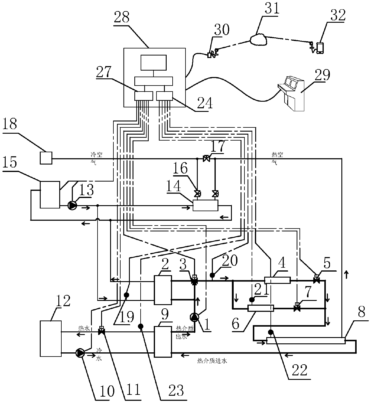
[0017] refer to figure 1 The embodiment of the centrifugal air compressor cascade waste heat recovery device of the present invention will be further described.

[0018] A cascaded waste heat recovery device for a centrifugal air compressor includes a primary heating medium circulating water part, a secondary heating circulating water part, a cooling circulating water part, a compressed air cooling part and an electrical control part.

[0019] The primary heat medium circulating water part includes heat medium circulating pump 1, cooling water temperature regulating heat exchanger 2, temperature regulating three-way regulating valve 3, secondary heating heat exchanger 9 and primary cooling of centrifugal air compressor 4, the secondary cooler 6 and the tertiary cooler 8, the outlet of the heat medium circulating pump 1 is divided into two routes and respectively connected to the water inlet of the cooling water temperature regulating heat exchanger 2 and the bypass port of the...


PUM


Abstract

The invention discloses a cascaded waste heat recovery device for a centrifugal air compressor. The cascaded waste heat recovery device comprises a primary heat medium circulating water part, a secondary heating circulating water part, a circulation cooling water part, a compressed air cooling part and an electric control part. Waste of energy sources is reduced, the heat production recovery rateof the centrifugal air compressor is high, and the centrifugal air compressor is protected better.

Description

technical field [0001] The invention belongs to the field of thermal energy utilization devices of centrifugal air compressors, and more specifically relates to a cascade waste heat recovery device of centrifugal air compressors. Background technique [0002] The centrifugal air compressor drives the gas to rotate at a high speed by the impeller, so that the gas generates centrifugal force. Due to the diffusion flow of the gas in the impeller, the flow rate and pressure of the gas after passing through the impeller are increased, and compressed air is continuously produced. Here During the process, a large amount of heat will be generated. The gas compression temperature is 120-180°C. Generally, it is cooled by the cooling water of the cooling tower, and the heat is discharged into the atmosphere through the cooling tower, causing energy waste and polluting the environment. The wasted heat is about To account for 80% of the power consumed by the motor. All this wasted heat ...

Claims


Application Information

Patent Timeline
Patent Type & Authority Applications(China)
IPC IPC(8): F04D29/58F04D27/00F04D15/00
CPCF04D15/0005F04D27/00F04D27/001F04D29/5833
Inventor 方奇杨林
Owner JIAXING SYANBO ENERGY SAVING TECH
Why Eureka
Try Eureka