A multi-injector group enhanced co 2 Dual temperature refrigeration system

A refrigeration system and ejector technology, applied in evaporator/condenser, refrigerator, refrigeration components, etc., can solve the problem of large throttling loss, and achieve the effect of recovering throttling loss, reducing quantity, and improving heat exchange efficiency

Active Publication Date: 2020-11-27
SHANDONG SHENZHOU REFRIGERATION EQUIP
View PDF13 Cites 0 Cited by
  • Summary
  • Abstract
  • Description
  • Claims
  • Application Information

AI Technical Summary

Problems solved by technology

However, the current use of ejectors has great limitations: the ejector fluid is gas; it can only adapt to a single working condition (especially the cooling capacity)
[0006] Related patents such as "A Transcritical CO2 Two-Stage Compression Booster Refrigeration System" (Application No. 201711290797.3) have proposed two-stage compression and expansion tanks to reduce the exhaust of compressed gas in response to the problem of excessive throttling losses in transcritical CO2 refrigeration systems. The temperature also reduces the throttling loss, but it is not aimed at the dual temperature refrigeration system used in supermarkets and does not use ejectors
Related patents such as "A mechanically assisted subcooling CO2 transcritical cooling and heating integrated system" (application number 201810093169.4) are aimed at the integrated cooling and heating system, and do not involve the issue of reducing throttling losses

Method used


Image

  • A multi-injector group enhanced co  <sub>2</sub> Dual temperature refrigeration system
  • A multi-injector group enhanced co  <sub>2</sub> Dual temperature refrigeration system
  • A multi-injector group enhanced co  <sub>2</sub> Dual temperature refrigeration system

Examples


Embodiment Construction

[0023] The present invention will be described in further detail below in conjunction with the accompanying drawings and specific embodiments.

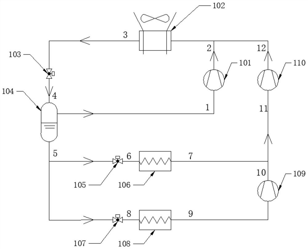
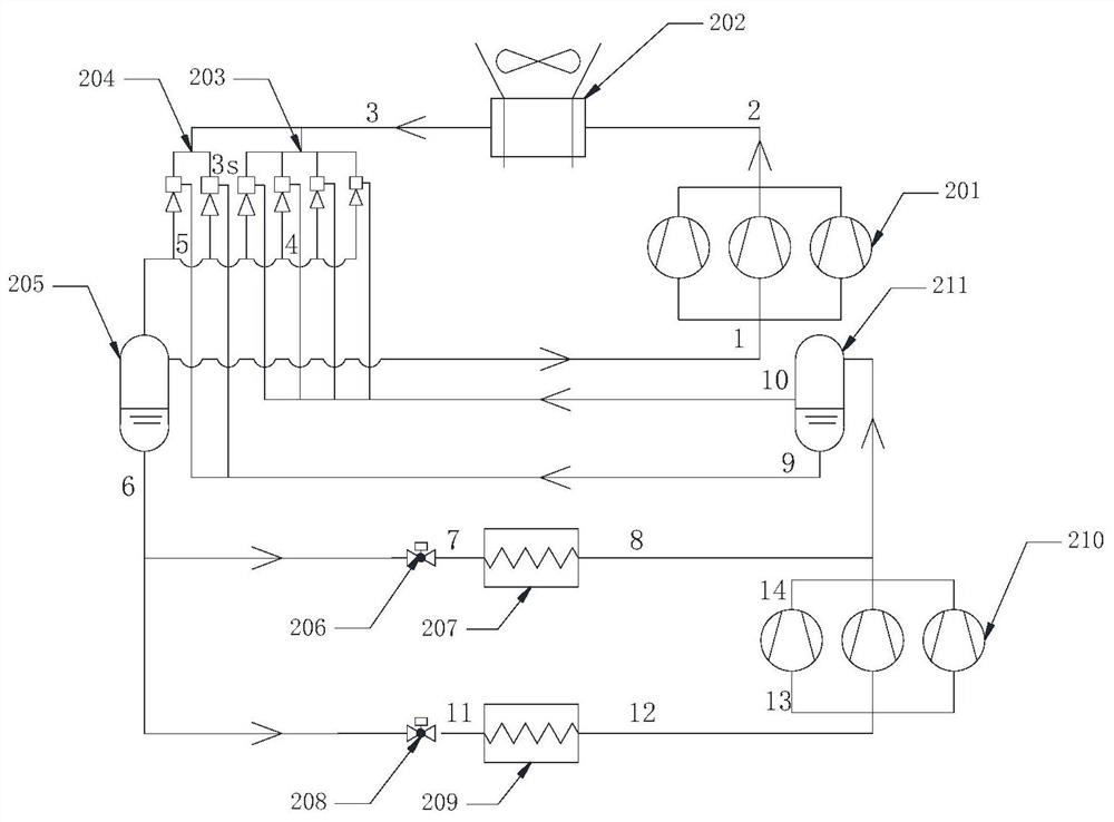
[0024] Such as figure 2 As shown, a multi-injector group enhanced CO of the present invention 2 Dual temperature refrigeration system, including:

[0025] High temperature compressor, gas cooler, gas-gas ejector group, gas-liquid ejector group, gas-liquid separator, first throttle valve, medium temperature evaporator, second throttle valve, low temperature evaporator, low temperature compressor , Liquid reservoir.

[0026]The high-temperature compressor is a CO2 transcritical compressor, and its outlet is connected to the inlet of the gas cooler; the outlet of the gas cooler is divided into two routes, one of which is connected to the first inlet of the gas-gas injector group, and the other is connected to the gas-gas ejector group. The first inlet of the liquid ejector group is connected; the second inlet of the gas-gas ejector g...


PUM


Abstract

The invention relates to a multi-injector group enhanced CO 2 In a transcritical dual-temperature refrigeration system, the outlet of the high-temperature compressor is connected to the inlet of the gas cooler; the outlet of the gas cooler is divided into two paths, one is connected to the first inlet of the gas-gas ejector group, and the other is connected to the gas-liquid The first inlet of the injector group is connected; the second inlet of the gas-gas ejector group is connected with the saturated gas outlet of the gas-liquid separator; the second inlet of the gas-liquid ejector group is connected with the saturated liquid outlet of the gas-liquid separator The outlets of the two sets of injectors are connected with the inlets of the accumulators; the outlets of the accumulators are divided into two paths, one is the saturated gas connected to the inlet of the high-temperature compressor, and the other is the saturated liquid connected to the first throttle valve respectively. It is connected with the inlet of the second throttle valve; the outlet of the first throttle valve is connected with the inlet of the medium temperature evaporator; the outlet of the medium temperature evaporator is connected with the inlet of the gas-liquid separator; the outlet of the second throttle valve is connected with the low temperature evaporator The outlet of the low-temperature evaporator is connected with the inlet of the low-temperature compressor; the outlet of the low-temperature compressor is connected with the inlet of the gas-liquid separator; the two outlets of the gas-liquid separator are respectively connected with the gas-gas ejector group and the gas - The second inlet of the liquid injector group is connected. in CO 2 Adding ejector group and flooded medium-temperature evaporator to the dual-temperature refrigeration system greatly improves the performance of the refrigeration system, and can better adapt to the national conditions of my country's high-temperature climate.

Description

technical field [0001] The invention relates to the field of refrigeration technology, in particular to a multi-ejector group enhanced CO 2 Dual-temperature refrigeration system, principle and application. Background technique [0002] Due to the ozone depletion caused by chlorofluorocarbons (CFCs) and hydrochlorofluorocarbons (HCFCs), and the impact of hydrofluorocarbons (HFCs) on global warming, 197 countries from all over the world have reached an agreement to reduce the emissions of chemical refrigerants. With the acceleration of the implementation process of the "Montreal Protocol" and the conclusion of the Kigali Amendment, it is expected that 88% of greenhouse gas emissions of hydrofluorocarbons (HFCs) will be reduced in the 21st century. In order to reduce the impact of chemical refrigerants on the environment, CO 2 As a natural refrigerant (ODP is 0, GWP is negligible), it has become an important refrigerant substitute. In fact, CO 2 It is the most environmental...

Claims


Application Information

Patent Timeline
Patent Type & Authority Patents(China)
IPC IPC(8): F25B9/08F25B39/02F25B41/06F25B43/00F25B41/30
CPCF25B9/08F25B39/02F25B43/00F25B41/30
Inventor 高晨晨赵红霞陈威宋明刚马训刚
Owner SHANDONG SHENZHOU REFRIGERATION EQUIP
Why Eureka
Try Eureka