Device for testing rigidity of semi-rigid bearing

A semi-rigid and bearing technology, which is applied in the field of devices for testing the stiffness of semi-rigid bearings, can solve the problems of inaccurate detection accuracy, inability to fully reflect the stiffness performance and offset of semi-rigid bearings

Inactive Publication Date: 2019-04-12
C&U CO LTD +1
View PDF6 Cites 5 Cited by
  • Summary
  • Abstract
  • Description
  • Claims
  • Application Information

AI Technical Summary

Problems solved by technology

[0002] Semi-rigid bearings are widely used in the fields of automobiles, home appliances, and mechanical equipment. The so-called semi-rigid bearings mean that the bearings contain related plastic parts, and the steel ball rings will move under load, so they are called It is semi-rigid, because it contains plastic parts, so testing the stiffness performance of semi-rigid bearings is a very important step before this kind of bearings leave the factory, because only knowing the stiffness properties of semi-rigid bearings can we determine where this type of bearings are suitable for installation. In such an environment, the existing stiffness testing device is difficult to fix the bearing to be tested, and the bearing is prone to slipping or shifting during testing, resulting in inaccurate testing accuracy, and the existing stiffness testing machine can only be tested from one direction Due to the stiffness of the bearing, the detected data cannot fully reflect the stiffness performance of the semi-rigid bearing

Method used


Image

  • Device for testing rigidity of semi-rigid bearing
  • Device for testing rigidity of semi-rigid bearing
  • Device for testing rigidity of semi-rigid bearing

Examples


Embodiment Construction

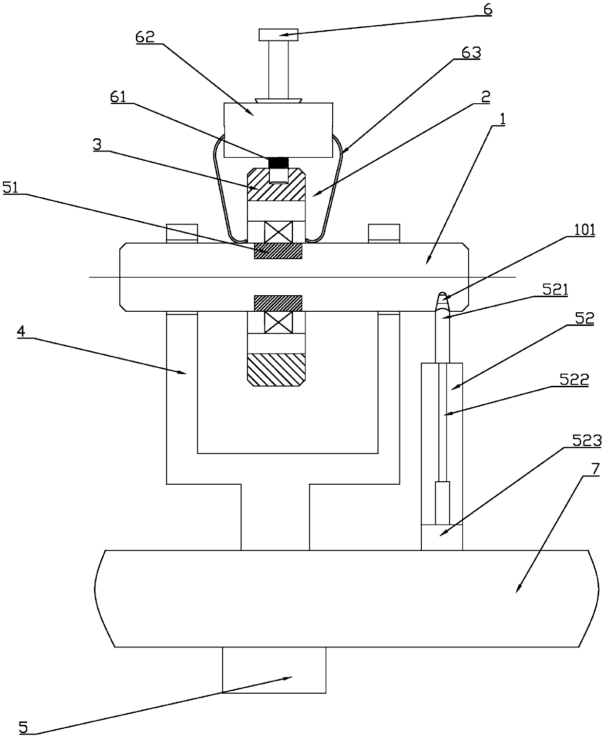
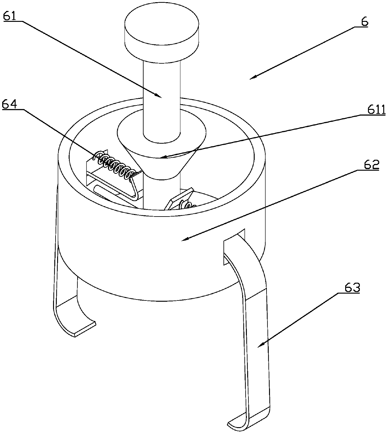
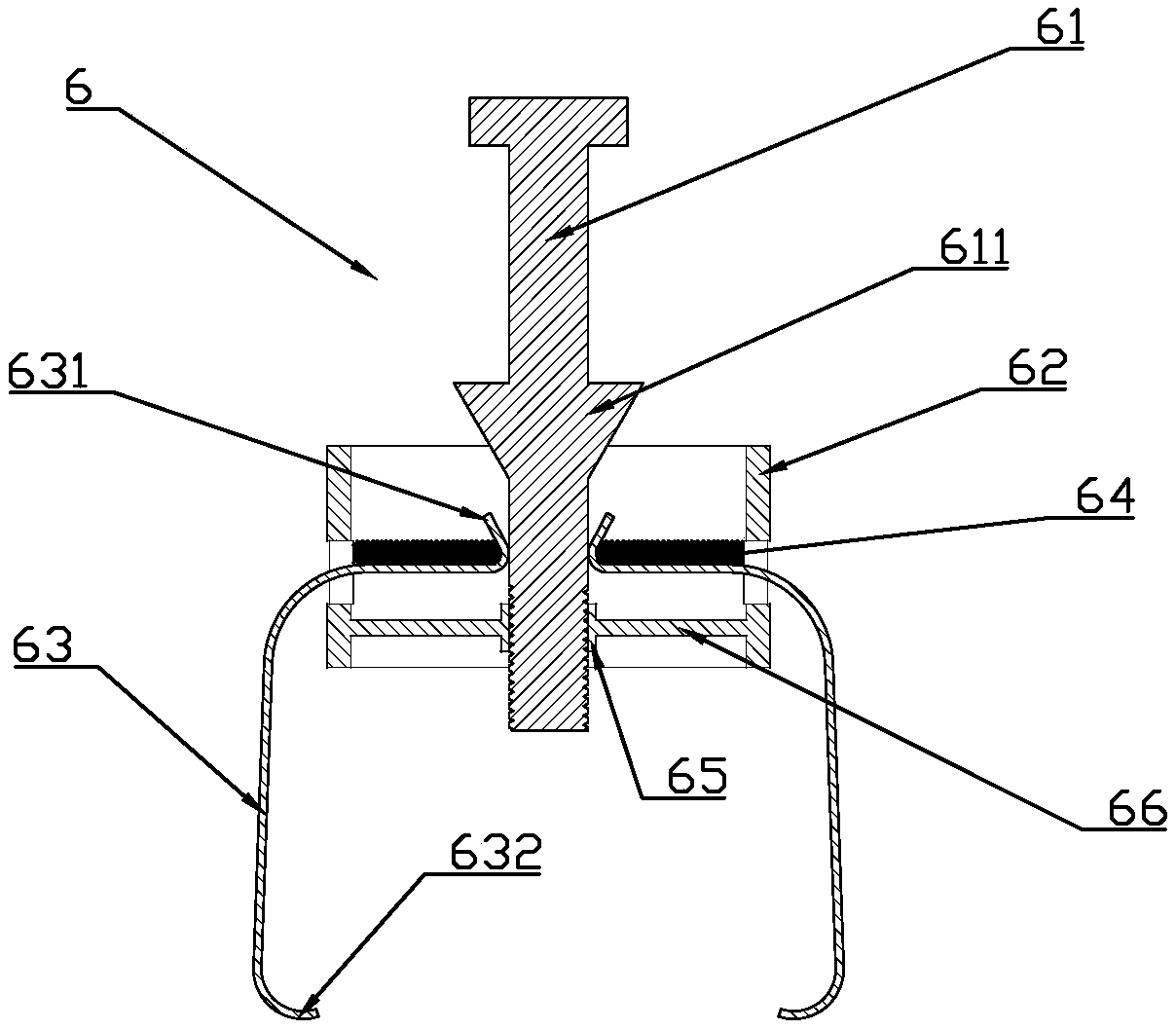
[0018] Depend on Figure 1 to Figure 4 It can be seen that the present invention discloses a device for detecting the stiffness of a semi-rigid bearing, which includes a driving member and a fixed assembly, a test shaft 1 is arranged between the driving member and the fixed assembly, and a test shaft 1 is provided with a Station 2, the station to be tested is provided with a fixed shell 3 for installing the bearing to be tested, and the drive member includes a connecting rod 4 arranged at both ends of the test shaft 1 and a device for driving the connecting rod 4 to slide. The hydraulic cylinder 5, the connecting rod 4 is engaged with the test shaft 1, the connection between the test shaft 1 and the station 2 to be tested is provided with a pressure sensor 51, and the test shaft 1 is provided with a pressure sensor 51 for detecting the displacement of the test shaft 1. The telescopic displacement sensor 52, the fixing assembly includes a fixing fixture 6, and the fixing fixtur...


PUM


Abstract

The invention discloses a device for testing rigidity of a semi-rigid bearing. The device for testing the rigidity of the semi-rigid bearing comprises a driving piece and a fixing assembly, wherein atesting shaft is arranged between the driving piece and the fixing assembly, a to-be-tested station is arranged on the testing shaft, and a fixing shell is arranged on the to-be-tested station; the driving piece comprises a connecting rod and a hydraulic cylinder, the connecting rod is matched with the testing shaft in a clamping connection mode, and a telescopic type displacement sensor and a pressure sensor are arranged on the testing shaft; the fixing assembly comprises a fixing clamping tool, and the fixing clamping tool comprises a threaded rod, an annular installing seat and two clampingjaws; the clamping jaws are hinged to the annular installing seat, one ends of the clamping jaws are located in the annular installing seat and abut against the threaded rod to form driving ends, andthe other ends of the clamping jaws are located on the two sides of the fixing shell to form clamping ends; and the threaded rod is matched with the fixing shell in a threaded mode, an inclined surface is arranged on the threaded rod, and the threaded rod and the annular installing seat are relatively slidably arranged. According to the device for testing the rigidity of the semi-rigid bearing, the effect of fixing a to-be-tested bearing is good, the testing data are comprehensive and exact, and the testing precision is high.

Description

[0001] The invention relates to the technical field of bearing detection, in particular to a device for detecting the stiffness of a semi-rigid bearing. Background technique [0002] Semi-rigid bearings are widely used in the fields of automobiles, home appliances, and mechanical equipment. The so-called semi-rigid bearings mean that the bearings contain related plastic parts, and the steel ball rings will move under load, so they are called It is semi-rigid, because it contains plastic parts, so testing the stiffness performance of semi-rigid bearings is a very important step before this kind of bearings leave the factory, because only knowing the stiffness properties of semi-rigid bearings can we determine where this type of bearings are suitable for installation. In such an environment, the existing stiffness testing device is difficult to fix the bearing to be tested, and the bearing is prone to slipping or shifting during testing, resulting in inaccurate testing accuracy, ...

Claims


Application Information

Patent Timeline
Patent Type & Authority Applications(China)
IPC IPC(8): G01M5/00
CPCG01M5/005
Inventor 李新旺何新宇
Owner C&U CO LTD
Why Eureka
Try Eureka