Stepping motor

A stepping motor and stator technology, applied in electric components, electrical components, electromechanical devices, etc., can solve the problems of high output torque requirements and limited motor installation space, and achieve the effect of increasing output torque, reducing height and increasing thickness

Pending Publication Date: 2019-04-12
GUANGZHOU RUIBAO ELECTRICAL CO LTD
View PDF0 Cites 0 Cited by
  • Summary
  • Abstract
  • Description
  • Claims
  • Application Information

AI Technical Summary

Problems solved by technology

The stepper motor increases its output torque without increasing the overall size, so as to solve the problem that the installation space for the motor will become more and more limited, but the requirement for output torque is getting higher and higher.

Method used


Image

  • Stepping motor
  • Stepping motor
  • Stepping motor

Examples


Embodiment 1

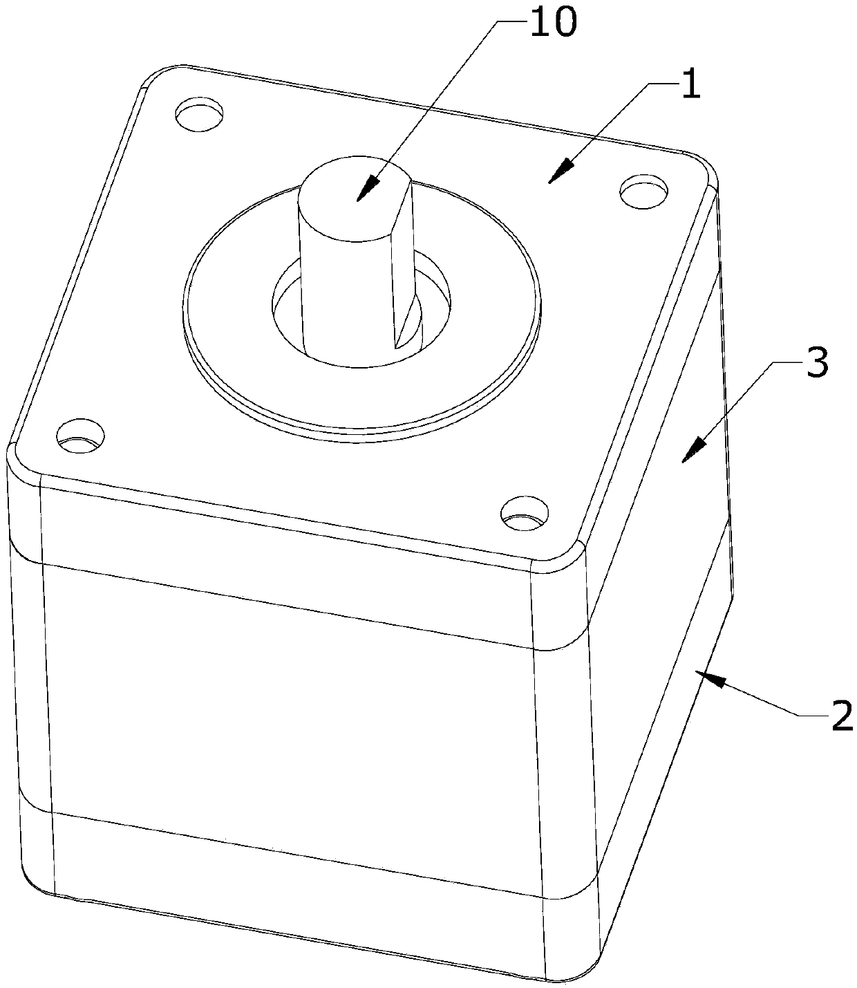
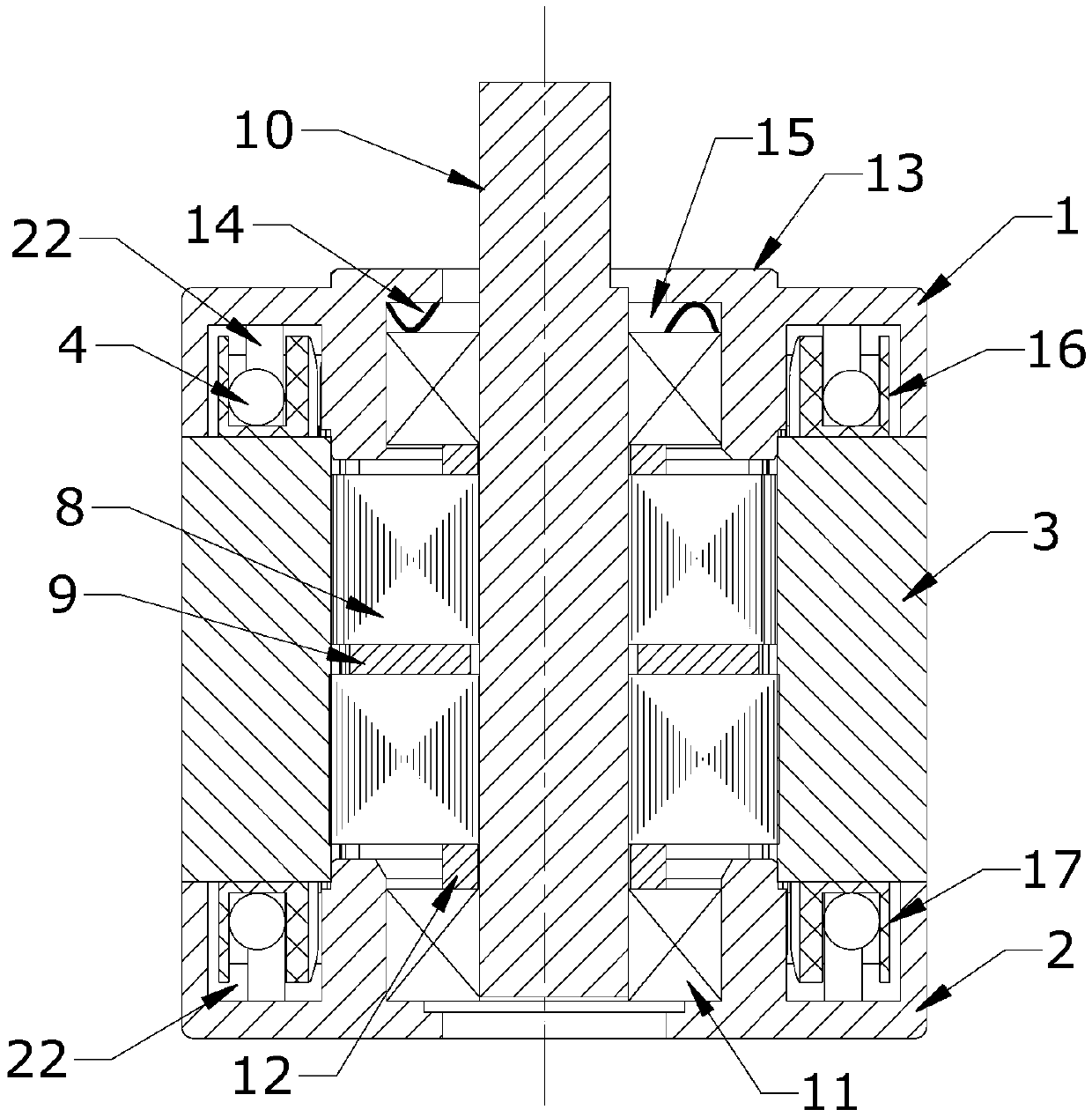
[0034] see figure 1 , figure 2 , The structure of the stepper motor in this embodiment includes a stator 3 assembly, a rotor assembly, a front end cover 1, and a rear end cover 2.

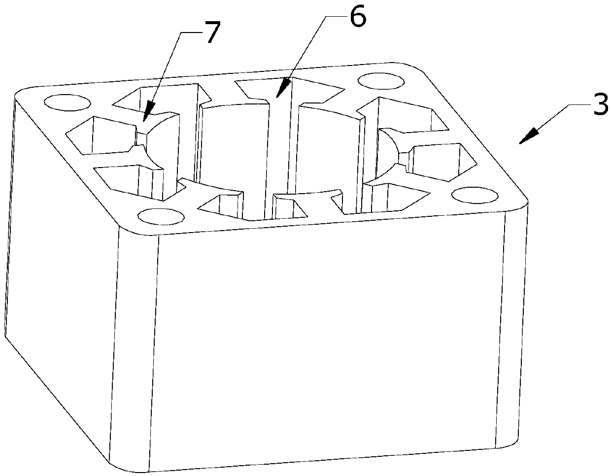
[0035] The stator 3 assembly includes a stator 3, an enameled wire 4, and an insulating end cover with legs 5 embedded in the winding slot 6 of the stator 3; the enameled wire 4 is wound on the insulating end cover to form a winding group for each magnetic pole 7 of the stator 3.

[0036] The rotor assembly includes a rotor piece 8, a magnetic steel 9, and a rotating shaft 10; the two ends of the rotating shaft 10 are respectively supported by the bearing 11 installed in the bearing 11 chamber of the front end cover 1, and the bearing 11 of the bearing 11 chamber of the rear end cover 2 . In this embodiment, the rotor assembly further includes a bushing 12 sleeved on the rotating shaft 10 and located between the bearing 11 and the rotor piece 8 . Since in this embodiment, the number of the roto...

Embodiment 2

[0043] Figure 6 , Figure 7 Shown is another embodiment of the stepper motor of the present invention. The stepping motor includes a stator 3 assembly, a rotor assembly, a front end cover 1 and a rear end cover 2 . In this embodiment, the structures of the stator 3 assembly, the rotor assembly, and the rear end cover 2 are exactly the same as those of the stepper motor in the embodiment, and will not be described in detail here.

[0044] In this embodiment, the front end cover 1 is basically the same as the front end cover 1 of the stepping motor in the embodiment, the difference is that the front end cover 1 is also provided with two opposite mounting ears 23, opposite to each other. Figure 6 Viewing angle, the two mounting ears 23 are respectively located on the left and right sides of the front cover 1 , and the mounting ears 23 are provided with screw holes 24 . The mounting holes of the front cover 1 of general stepping motors are common to the screw holes for fixing...


PUM


Abstract

The invention relates to a stepping motor, which comprises a stator assembly, a rotor assembly, a front cover and a rear cover. The stator assembly comprises a stator, an enameled wire, and an insulated end cover of which the legs are embedded in winding grooves of the stator. The enameled wire is wound on the insulating end cover to form a winding group of each magnetic pole of the stator. The rotor assembly comprises rotor plates, magnet steel and a rotating shaft. The two ends of the rotating shaft are respectively supported by a bearing installed in the bearing chamber of the front cover and a bearing in the bearing chamber of the rear cover. The front cover is provided with a first mounting platform protruding outwardly, the inner side of the first mounting platform is provided with an elastic cushion accommodating chamber for accommodating a spring washer, the elastic cushion accommodating chamber communicates with the bearing chamber located at the front cover, the output end ofthe rotating shaft sequentially passes through the bearing of the bearing chamber located at the front cover, the spring washer located at the elastic cushion accommodating chamber, and the shaft outlet hole on the first mounting platform. The stepping motor can improve the output torque without increasing the overall size.

Description

technical field [0001] The invention relates to the technical field of motors, in particular to a stepping motor. Background technique [0002] A stepper motor is an open-loop control motor that converts electrical pulse signals into angular displacement or linear displacement. As an actuator, the stepper motor is one of the key products of mechatronics and is widely used in various automation control systems. With the development of microelectronics and computer technology, the demand for stepper motors is increasing day by day, and they are used in various national economic fields. [0003] With the development of the times, all kinds of products are changing to small and exquisite routes, and most products that require power systems will have more and more limited installation space reserved for motors, but the requirements for output torque are getting higher and higher. Contents of the invention [0004] The purpose of the present invention is to provide a stepping ...

Claims


Application Information

Patent Timeline
Patent Type & Authority Applications(China)
IPC IPC(8): H02K1/12H02K1/27H02K5/16H02K5/04H02K5/08H02K3/46
CPCH02K1/12H02K1/2706H02K3/46H02K5/04H02K5/08H02K5/161
Inventor 王小林
Owner GUANGZHOU RUIBAO ELECTRICAL CO LTD
Why Eureka
Try Eureka