IQ signal calibration compensation method
A compensation method and signal technology, applied in the field of communication, can solve the problems of complex calculation process of blind calibration algorithm, complex calibration method, poor anti-interference ability, etc., so as to reduce logic complexity, simplify operation complexity, and increase stability. Effect
- Summary
- Abstract
- Description
- Claims
- Application Information
AI Technical Summary
Problems solved by technology
Method used
Image
Examples
specific Embodiment approach
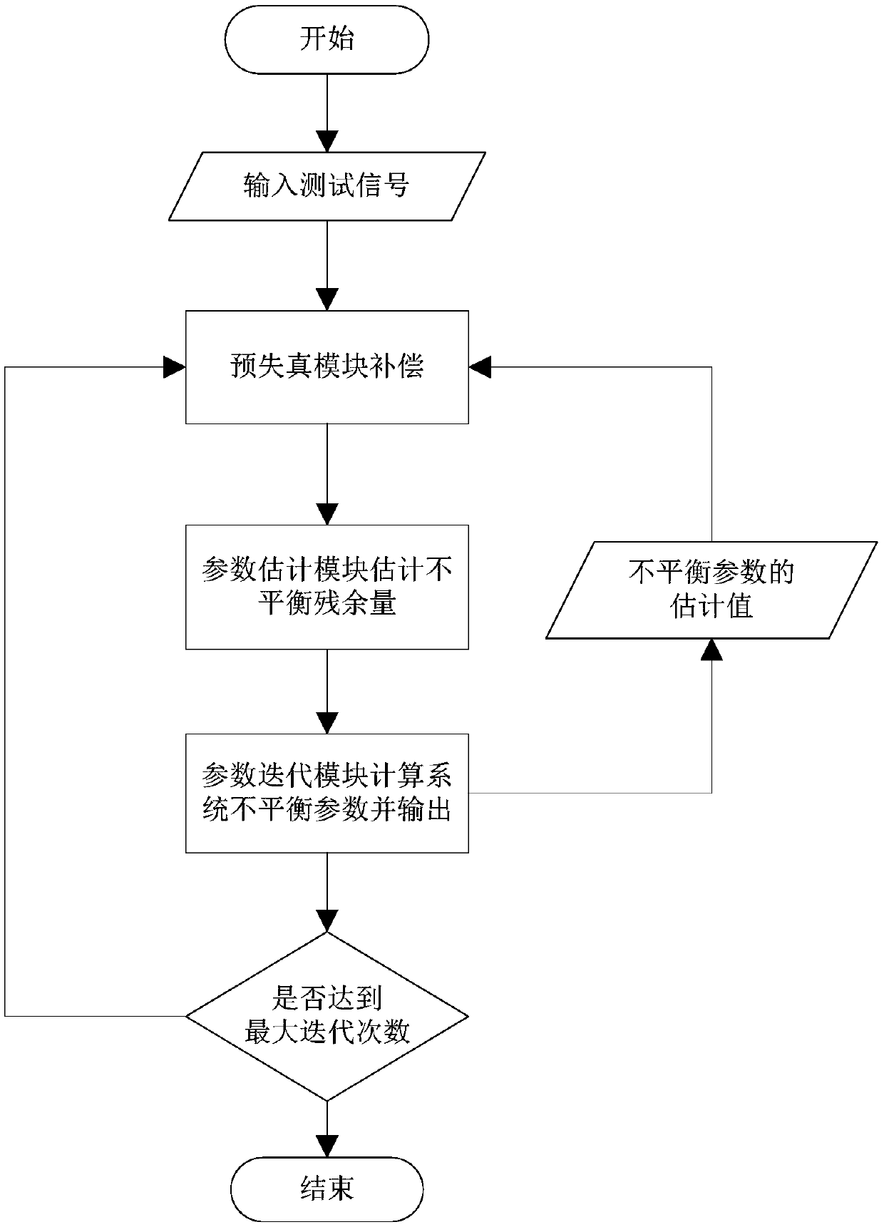
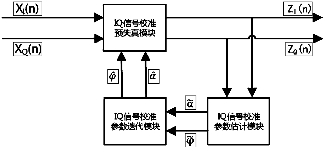
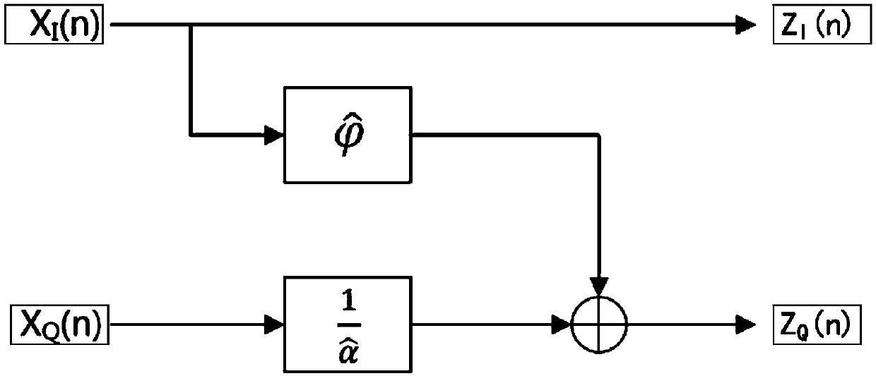
[0029] In order to solve the above problems, the present invention proposes a method for calibrating and compensating IQ signals, which is used for calibrating IQ signals of zero-IF receivers in wireless communication systems, figure 1 It is a schematic flow chart of the IQ signal calibration method provided by the technical solution of the present invention. figure 2 It is a schematic diagram of the principle of IQ signal calibration and compensation in the embodiment of the present invention. The method comprises the steps: (a) input calibration test signal to quadrature modulation (IQ) signal calibration predistortion module, calibration test signal comprises I road (in-phase) test signal X I And the Q way (orthogonal) test signal X Q ; (b) quadrature modulation (IQ) signal calibration predistortion module outputs compensation test signal (comprising I road compensation test signal Z by compensation calculation) I and Q compensation test signal Z Q ), the compensation c...
Embodiment 1
[0062] The preferred embodiments of the present invention will be described in detail below using specific data and parameters. The preferred embodiments described below are only used to illustrate and explain the present invention, and are not intended to limit the present invention.
[0063] Set the digital frequency of the calibration test signal in step (a) to 1 / 8F S , and Gaussian white noise is added to the signal, the signal-to-noise ratio (SNR) is 30dB, the amplitude imbalance parameter α is 1.1, and the phase imbalance parameter 0.1rad, so that the received signal amplitude A = 1. Figure 4 is the time-domain image of the calibration test signal I and Q channels. Figure 5 is the complex spectrum of the received test signal. Figure 5 , the spectral line corresponding to the abscissa 0.25 represents the useful signal spectrum, and its spectral intensity is 28.26dB, and the spectral line corresponding to the abscissa 1.75 represents the image signal spectrum caused ...
PUM
 Abstract
Description
Claims
Application Information
 - R&D
- Intellectual Property
- Life Sciences
- Materials
- Tech Scout
- Unparalleled Data Quality
- Higher Quality Content
- 60% Fewer Hallucinations
Browse by: Latest US Patents, China's latest patents, Technical Efficacy Thesaurus, Application Domain, Technology Topic, Popular Technical Reports.
© 2025 PatSnap. All rights reserved.Legal|Privacy policy|Modern Slavery Act Transparency Statement|Sitemap|About US| Contact US: help@patsnap.com


