Intermittent feeding and distributing device for animal husbandry
A technology of animal husbandry and feeding, which is applied in the field of intermittent feeding and batching devices for animal husbandry, can solve the problems of mixed livestock feeding nutrition imbalance, livestock feeding nutrition imbalance, low work efficiency, etc., to shorten the stirring time and ensure the mixing The effect of uniformity and high work efficiency
- Summary
- Abstract
- Description
- Claims
- Application Information
AI Technical Summary
Problems solved by technology
Method used
Image
Examples
specific Embodiment approach 1
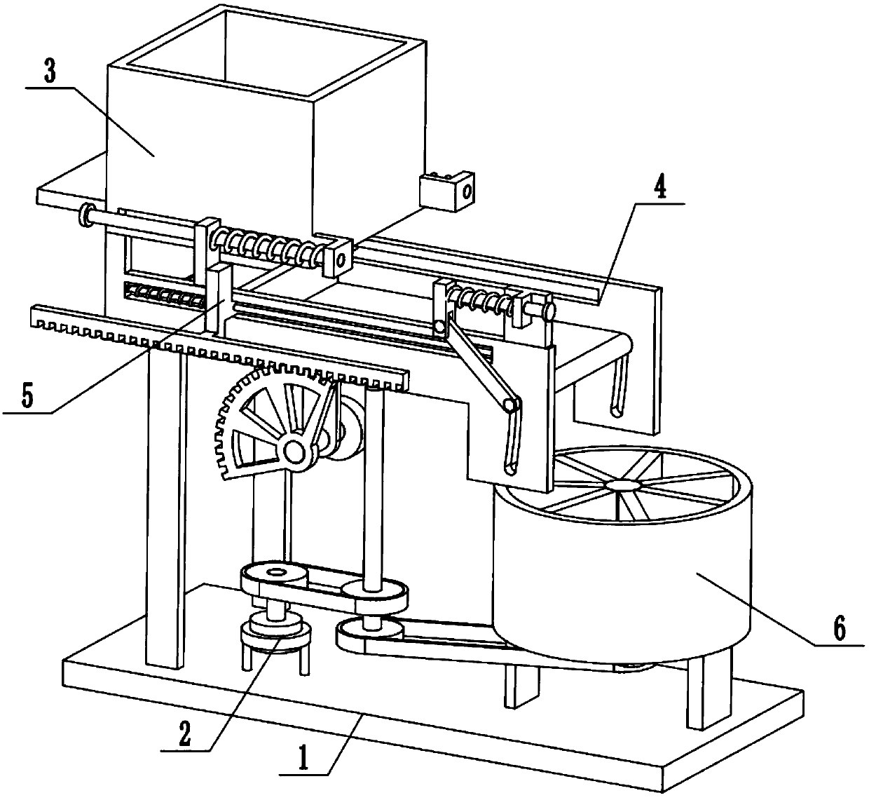
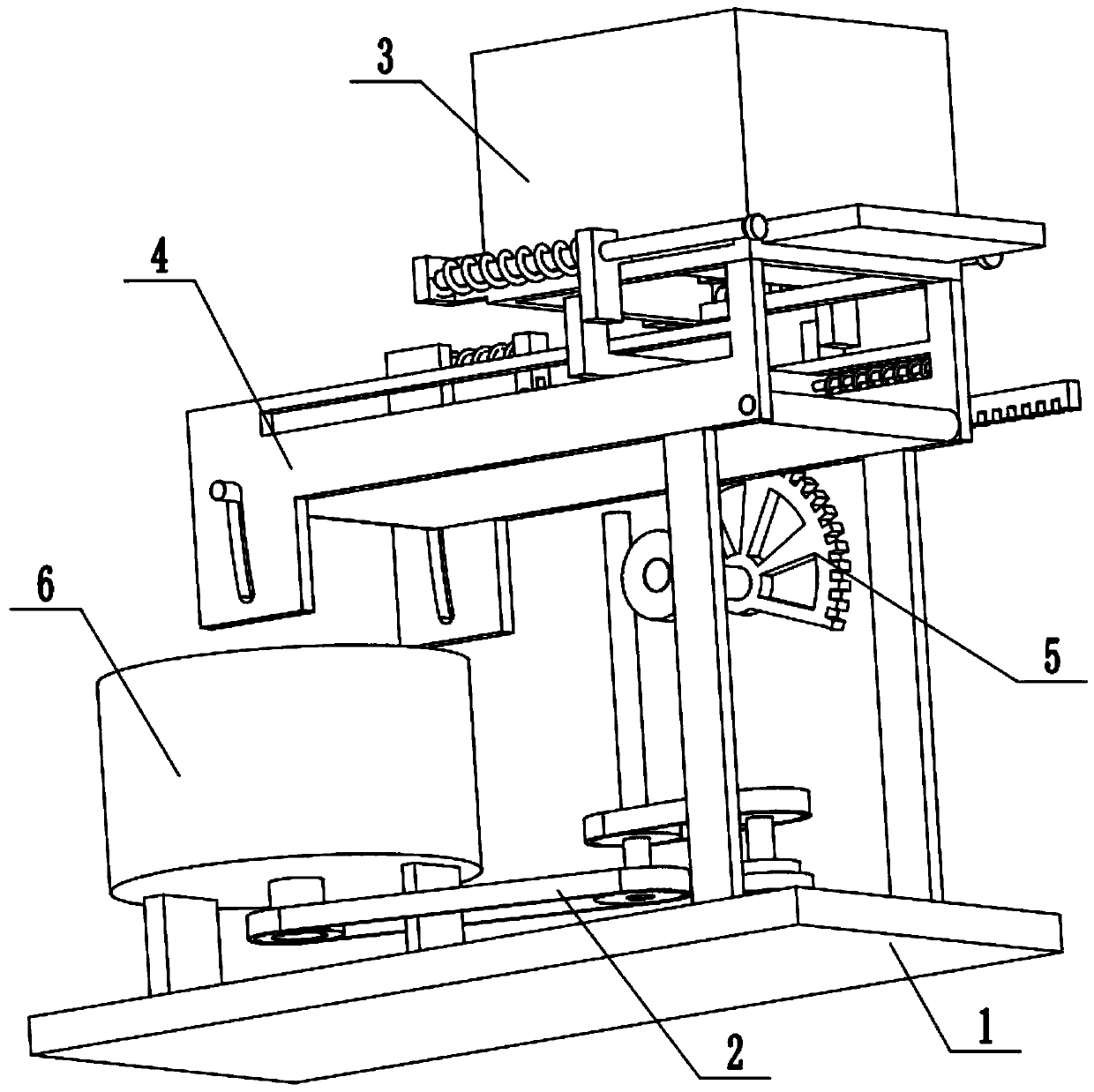
[0024] Combine below Figure 1-8 Description of this embodiment, an intermittent feeding batching device for animal husbandry, including a base 1, a power device 2, a feeding seat assembly 3, a blanking plate assembly 4, an intermittent pushing plate 5 and a stirring assembly 6, the feeding The material seat assembly 3 is fixedly connected to the left end of the blanking plate assembly 4, the left end of the base 1 is fixedly connected to two support plates 1-1, the left end of the blanking plate assembly 4 is fixedly connected to the two support plates 1-1, and the intermittent push The blanking plate 5 is slidingly connected to the blanking plate assembly 4, the upper end of the intermittent pushing plate 5 is attached to the feeding seat assembly 3, the blanking plate assembly 4 is meshed with the power unit 2, and the power unit 2 is fixedly connected to the base 1 Above, the power unit 2 is connected to the stirring assembly 6 through a belt drive, the stirring assembly 6...
specific Embodiment approach 2
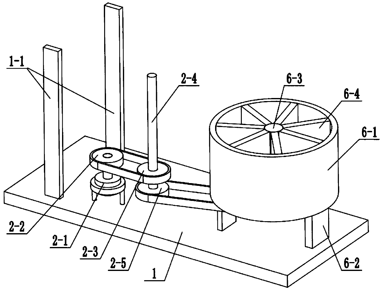
[0025] Combine below Figure 1-8 Describe this embodiment, described power unit 2 comprises motor 2-1, driving pulley 2-2, driven pulley 2-3, worm screw 2-4 and driving pulley 2-5; Motor 2-1 passes motor The frame is fixedly connected to the base 1, the output shaft of the motor 2-1 is fixedly connected to the driving pulley 2-2, the driving pulley 2-2 is connected to the driven pulley 2-3 through a belt transmission, and the driven pulley 2- 3 and the driving pulley 2-5 are fixedly connected to the worm 2-4, the lower end of the worm 2-4 is rotatably connected to the base 1 through a bearing with seat, and the upper end of the worm 2-4 is meshed with the intermittent pusher plate 5 for transmission connection , the driving pulley 2-5 is connected with the stirring assembly 6 through a belt transmission. When the power device 2 is in use, the motor 2-1 is connected to the power supply and the control switch through a wire and turned on. The motor 2-1 drives the driving pulley...
specific Embodiment approach 3
[0026] Combine below Figure 1-8To illustrate this embodiment, the stirring assembly 6 includes a stirring box 6-1, a vertical plate 6-2, a stirring shaft 6-3, a stirring plate 6-4 and a transmission pulley 6-5; the stirring box 6-1 passes through two The vertical plate 6-2 is fixedly connected to the right end of the base 1, the middle end of the stirring shaft 6-3 is rotatably connected to the center of the inner bottom surface of the stirring box 6-1 through a bearing with seat, and multiple stirring plates 6-4 and transmission pulleys 6- 5 are respectively fixedly connected to the upper and lower ends of the stirring shaft 6-3, the stirring plate 6-4 is rotatably connected in the stirring box 6-1, and the driving pulley 6-5 is connected to the driving pulley 2-5 through belt transmission; 6-1 The eccentric position of the bottom surface is fixedly connected and communicated with a short discharge pipe, and the lower end of the short discharge pipe is connected to the end c...
PUM
 Abstract
Description
Claims
Application Information
 - R&D
- Intellectual Property
- Life Sciences
- Materials
- Tech Scout
- Unparalleled Data Quality
- Higher Quality Content
- 60% Fewer Hallucinations
Browse by: Latest US Patents, China's latest patents, Technical Efficacy Thesaurus, Application Domain, Technology Topic, Popular Technical Reports.
© 2025 PatSnap. All rights reserved.Legal|Privacy policy|Modern Slavery Act Transparency Statement|Sitemap|About US| Contact US: help@patsnap.com


