
Sieving machine for chemical raw materials

A technology for chemical raw materials and screening, which is applied in the fields of filtration, solid separation, chemical instruments and methods, etc., and can solve problems such as inability to perform uniform blanking

Pending Publication Date: 2019-04-16
韩天信
View PDF9 Cites 3 Cited by
  • Summary
  • Abstract
  • Description
  • Claims
  • Application Information

AI Technical Summary

Problems solved by technology

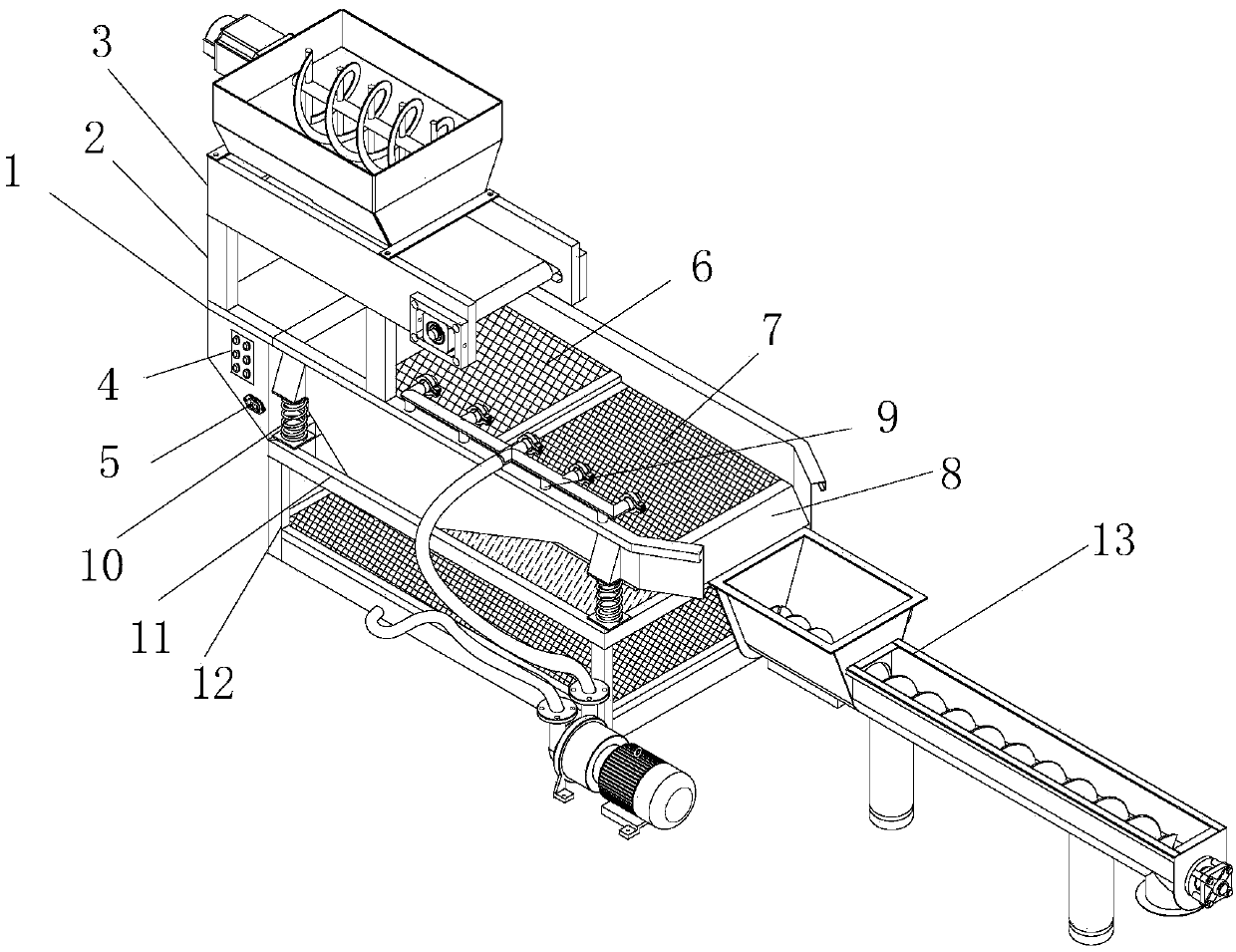
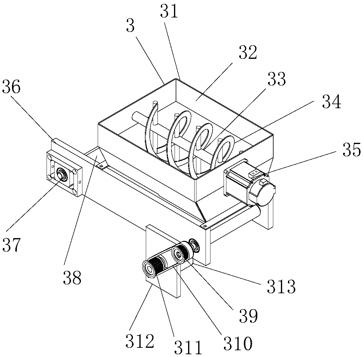
[0009] The present invention provides a chemical raw material screening machine through improvement. When the chemical raw material needs to be screened, there is agglomeration phenomenon in the raw material, which needs to be dispersed in advance, and the raw material that needs to be processed is sent from the pretreatment device. The separation bucket is poured in, and then the first motor is started by the control button on the controller to start working. The output shaft on the left side of the first motor can drive the main shaft to make the stirring blades rotate at high speed, and quickly break up the agglomerated raw materials, and then The raw material falls into the upper end of the conveyor belt at the bottom, and the second motor starts to work by the control button on the controller. The output shaft at the front end of the second motor drives the second pulley to rotate. When the second pulley rotates, the first pulley can be driven by the belt. When the first pulley rotates, the transmission rod can drive the conveyor belt to move, and then the raw materials on the conveyor belt can evenly fall on the first screen in the machine body, which solves the problem of raw materials clumping and has no pre-breaking function And the problem of not being able to evenly drop materials; after the screening work is completed, the screen in the body needs to be cleaned, the user pours water into the plate in the circulating cleaning device, and then starts the water pump by the control button on the controller Start to work, the water pump pumps the water source in the water outlet from the water inlet to the water pipe. During the pumping process, the water will go to the filter group, and the filter group is equipped with a primary filter, a deodorizing filter and an activated carbon filter. The three have strong filtering ability, can filter the water source layer by layer, and finally flow into the water outlet for extraction by the suction pipe, then discharge from the drain port to the drain pipe into the connecting pipe, and then connect the pipe to the sprinkler head for spraying out, the screen can be efficiently cleaned, and the water in the cleaning process falls into the water filter plate to filter out impurities, and then falls into the plate body, so as to circulate, achieving the effect of circular cleaning, and the cleaning effect of the equipment is poor. Difficult to clean and poor environmental protection; due to the large amount of raw materials, long-distance uniform discharge cannot be carried out. The raw materials flowing out of the discharge hopper are discharged into the feed hopper in the discharge device, and then the third motor is started to work, and the output shaft on the left side of the third motor It can drive the second gear to rotate. When the second gear rotates, it can drive the first gear to rotate through the chain. When the inner middle part of the first gear rotates, it drives the auger to move through the shaft seat, and the auger drives the raw material to rotate. The excess water in the raw material is discharged from the water filter net to the water outlet, and finally the raw material can be discharged through the discharge pipe to complete the discharge work, which solves the problem of poor uniformity and inconvenient long-distance discharge during discharge.

Method used


Image

  • Sieving machine for chemical raw materials
  • Sieving machine for chemical raw materials
  • Sieving machine for chemical raw materials

Examples


Embodiment Construction

[0042] The following will be combined with Figure 1-7 The present invention is described in detail, and the technical solutions in the embodiments of the present invention are clearly and completely described. Apparently, the described embodiments are only some of the embodiments of the present invention, not all of them. Based on the embodiments of the present invention, all other embodiments obtained by persons of ordinary skill in the art without making creative efforts belong to the protection scope of the present invention.

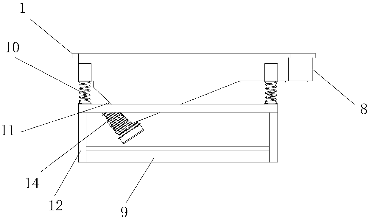
[0043] The present invention provides a chemical raw material screening machine through improvement, including a body 1, a controller 4, a power interface 5, a first screen 6, a second screen 7, a discharge hopper 8, a compression spring 10, and a water filter plate 11. Support rod 12, vibration motor 14, support arm 2, pretreatment device 3, circulation cleaning device 9 and discharge device 13, the left end of the top of the body 1 is vertically w...


PUM


Abstract

The invention discloses a sieving machine for chemical raw materials. The sieving machine for the chemical raw materials comprises a machine body, a controller, a power interface, a first sieve screen, a second sieve screen, a discharge hopper, a compression spring, a pretreatment device, a cyclic cleaning device and a discharge device, wherein the raw materials needing to be processed are pouredin from a separation hopper on the pretreatment device; a first motor is started to start to work; a main shaft is driven to enable stirring blades to carry out high-speed rotation; the agglomerated raw materials are rapidly dispersed and then fall onto the upper end of a conveying belt at the bottom; a second motor is started to start to work; a front-end output shaft of the second motor drives asecond belt wheel to rotate; a first belt wheel is enabled to rotate through the belt during the rotation of the second belt wheel; a transmission rod is enabled to drive the conveying belt to move during the rotation of the first belt wheel; and then the raw materials on the conveying belt are capable of uniformly falling onto the first sieve screen in the machine body. The problems of an agglomeration phenomenon of raw materials, no pre-dispersing function and incapacity of carrying out uniform falling are solved.

Description

technical field [0001] The invention relates to the field of chemical machinery, in particular to a chemical raw material screening machine. Background technique [0002] Chemical machinery is the general term for machines and equipment used in chemical industrial production. In order to process raw materials into finished products of a certain specification in chemical production, it often needs to go through a series of chemical processes such as raw material pretreatment, chemical reaction, and separation and purification of reaction products. The machinery used to realize these processes is often classified as chemical machinery, and special screening devices are required for pretreatment of raw materials. Generally, vibrating screen devices are used for efficient screening of raw materials. [0003] However, the existing chemical raw material screening machinery has the following problems: [0004] 1. The existing chemical raw material screening machinery has agglomera...

Claims


Application Information

Patent Timeline
IPC IPC(8): B07B1/28B02C13/02B07B1/55C02F9/02
CPCB02C13/02B07B1/28B07B1/55C02F1/001C02F1/283C02F9/00C02F2303/02
Inventor 韩天信
Owner 韩天信
Learn More