Pipe bending device for air conditioner refrigeration copper pipe

A pipe bending device, air-conditioning and refrigeration technology, applied in the direction of feeding device, positioning device, storage device, etc., can solve the problems of long protruding length of copper pipe at the port, excessive length difference, deviation of bending pipe length, etc., and achieve production efficiency The effect of high height, small angle deviation and small deformation of copper tube

Inactive Publication Date: 2019-04-16
吴登科
View PDF5 Cites 4 Cited by
  • Summary
  • Abstract
  • Description
  • Claims
  • Application Information

AI Technical Summary

Problems solved by technology

[0003] The radiator is composed of many U-shaped tubes. The length of each U-shaped tube and the length of the two ends of each U-shaped tube have very high consistency requirements. When bending U-shaped tubes, due to equipment or adjustments The length of each U-shaped tube and the length difference between the two ends of each U-shaped tube are too large (greater than 2mm), so when the port is too long, the extension length of the copper tube is too long and the flaring is too large. while cracking
Therefore, in order to bend the metal pipe to the set value, it is necessary to visually measure the angle of the pipe bend and make multiple adjustments in the traditional pipe bending process. Multiple adjustments not only cause large deviations in the length of the pipe bend, but also make it difficult to guarantee the quality, and are time-consuming and laborious. , low production efficiency

Method used


Image

  • Pipe bending device for air conditioner refrigeration copper pipe
  • Pipe bending device for air conditioner refrigeration copper pipe
  • Pipe bending device for air conditioner refrigeration copper pipe

Examples


Embodiment Construction

[0023] The following will clearly and completely describe the technical solutions in the embodiments of the present invention with reference to the accompanying drawings in the embodiments of the present invention. Obviously, the described embodiments are only some, not all, embodiments of the present invention. Based on the embodiments of the present invention, all other embodiments obtained by persons of ordinary skill in the art without making creative efforts belong to the protection scope of the present invention.

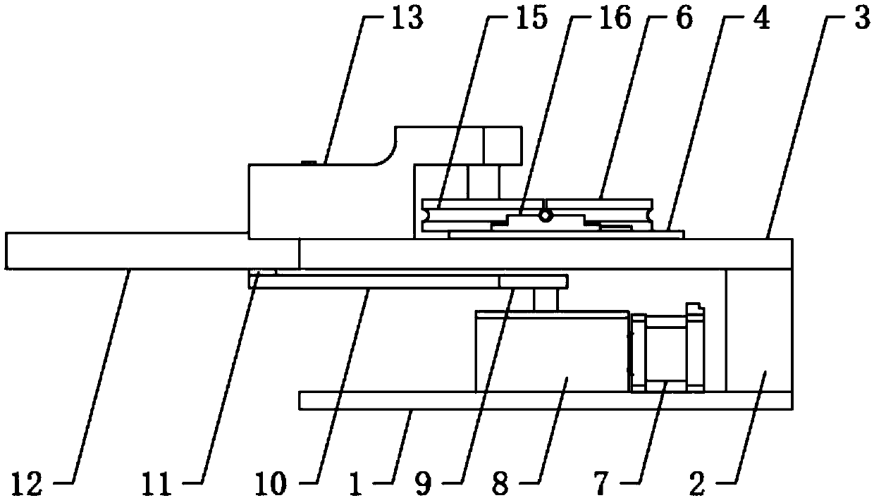
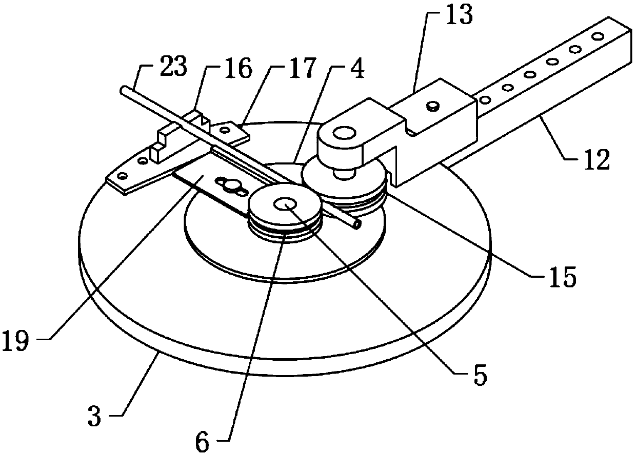
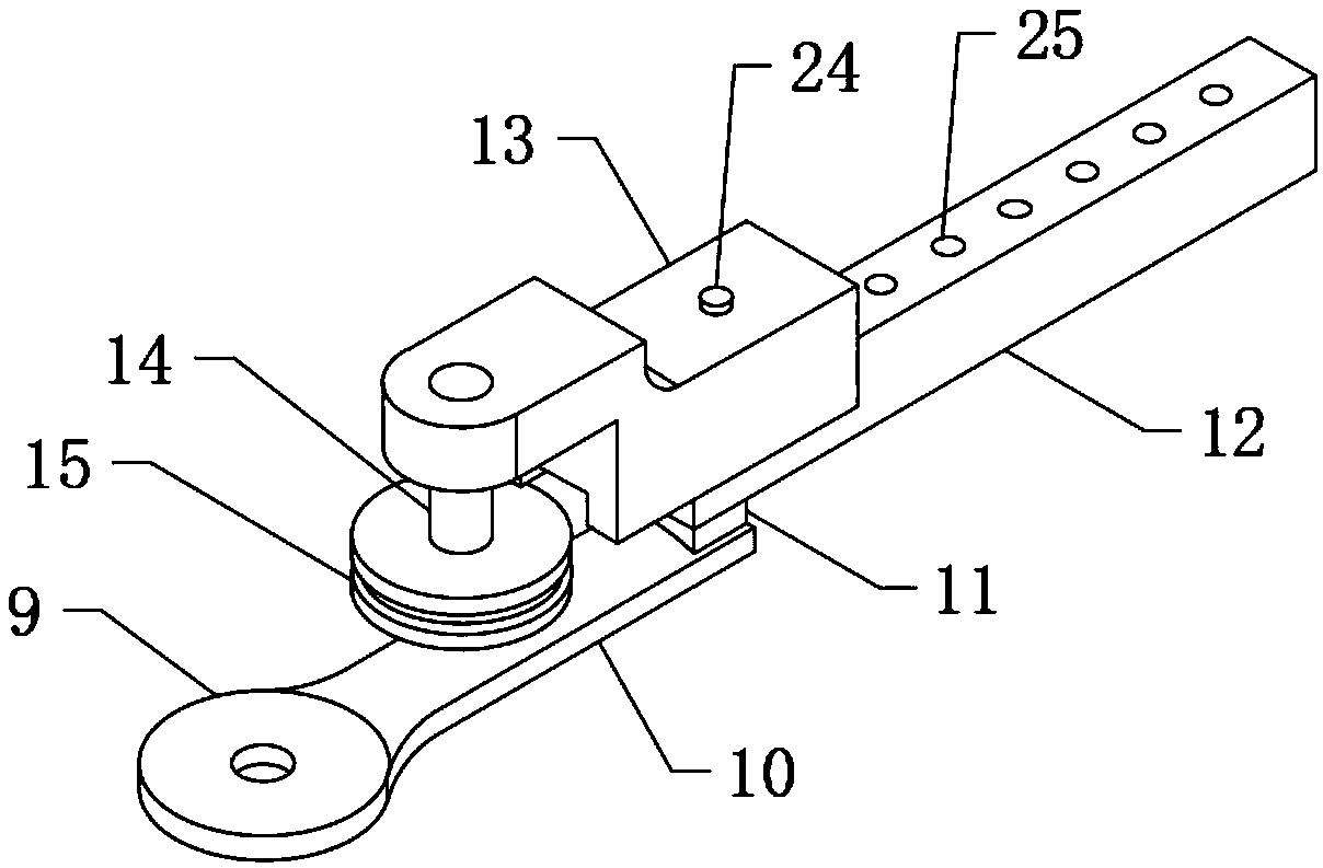
[0024] see Figure 1 to Figure 5 , the present invention provides a technical solution: a pipe bending device for air-conditioning refrigeration copper pipes, including a base 1, a driving device, a pipe bending device and a positioning device, the base 1 is fixedly connected to a column 2, and the column 2 is fixedly connected to a large disc 3. The large disk 3 is fixedly connected to the small disk 4, and the small disk 4 is fixedly connected to the positio...


PUM


Abstract

The invention discloses a pipe bending device for an air conditioner refrigeration copper pipe. The pipe bending device comprises a base, a driving device, a pipe bending device body and a positioningdevice, the base is fixedly connected with a vertical column, the vertical column is fixedly connected with a large disc, the large disc is fixedly connected with a small disc, the small disc is fixedly connected with a positioning pin, the positioning pin is connected with a fixed wheel in a sleeved mode, the pipe bending device body comprises a rotating disc, the rotating disc rotates by a specified angle through the driving device, the rotating disc is fixedly connected with a connecting rod, the connecting rod is fixedly connected with an arc-shaped block, the arc-shaped block is fixedlyconnected with a distance-fixed rod, and an adjusting block is placed on the distance-fixed rod and provided with a movable wheel. The pipe bending device is concise in structure and small in occupiedspace, the length that the movable wheel rotates around the fixed wheel can be adjusted by replacing the fixed wheels with the different diameters, thus the pipe bending device adapts to the demandsof different pipe bending lengths, the copper pipe can be bent to the set length at a time, angle adjusting for multiple times of pipe bending is reduced, the fixed wheels are conveniently replaced and adjusted, the time and labor are saved, and the production efficiency of bent pipes is high.

Description

technical field [0001] The invention relates to the technical field of pipe bending devices, in particular to a pipe bending device used for air-conditioning refrigeration copper pipes. Background technique [0002] An air conditioner is mainly composed of a compressor, a radiator, and an automatic control system. The copper tube in the radiator is called the blood vessel of the air conditioner in the industry. The quality of the blood vessel will directly determine the quality of the air conditioner. Traditionally, there are two processes for making copper tubes: cutting-bending-expanding-cleaning-welding-pressure testing. [0003] The radiator is composed of many U-shaped tubes. The length of each U-shaped tube and the length of the two ends of each U-shaped tube have very high consistency requirements. When bending U-shaped tubes, due to equipment or adjustments The length of each U-shaped tube and the length difference between the two ends of each U-shaped tube are too ...

Claims


Application Information

Patent Timeline
Patent Type & Authority Applications(China)
IPC IPC(8): B21D7/024B21D7/12B21D43/00B21D53/06
CPCB21D7/024B21D7/12B21D43/003B21D53/06
Inventor 吴登科
Owner 吴登科
Why Eureka
Try Eureka