Combustion type steel component oriented cutting device

A technology for cutting devices and components, applied in aluminothermic welding equipment, welding equipment, metal processing equipment, etc., can solve the problems of unsafety, poor orientation, high energy consumption, etc., and achieve fast combustion reaction speed, fast cutting rate, and energy consumption low effect

Active Publication Date: 2019-04-16
ARMY ENG UNIV OF PLA
View PDF11 Cites 1 Cited by
  • Summary
  • Abstract
  • Description
  • Claims
  • Application Information

AI Technical Summary

Problems solved by technology

[0007] The purpose of the present invention is to provide a directional cutting device for combustion-shaped steel members in view of the deficiencies of the prior art, so as to solve the problem of using high-sensitivity pyrotechnic element priming in the prior art, and there are unsafe factors during storage and transportation. Problems with long-distance operation, poor orientation, and high energy consumption

Method used


Image

  • Combustion type steel component oriented cutting device
  • Combustion type steel component oriented cutting device
  • Combustion type steel component oriented cutting device

Examples


Embodiment 1

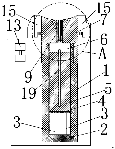
[0036] Example 1. Such as Figure 1-8 As shown, a directional cutting device for combustion-shaped steel members is characterized in that: it includes a charge barrel 1, and the charge barrel 1 is sequentially provided with a bottom support sleeve 3, a top plate 4 with a circular cross section, and a cutting agent Layer 5, igniting agent layer 6, the central axis of the bottom support sleeve 3 coincides with the central axis of the charge barrel 1; the radial outer peripheral surface of the top plate 4 is close to the radial inner peripheral surface of the charge barrel 1; the top plate 4 is placed on On the bottom support sleeve 3; the bottom support sleeve 3 is placed on the barrel bottom 2 of the charge barrel 1; the top cover 7 that can seal the top opening of the charge barrel 1 is installed on the top of the charge barrel 1; the diameter of the top cover 7 The outer peripheral surface is provided with a fixing device 15 for fixing the top cover 7 on the object 20 to be ...

Embodiment 2

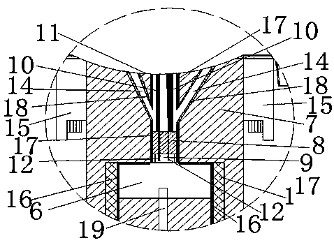
[0047] Example 2. Such as Figure 9-10 As shown, the difference between this embodiment and Embodiment 1 is that the fixing device 15 is a plurality of mounting ears provided on the top cover 7 , and each mounting ear is provided with a magnet 21 . The cross section of the object 20 to be punched is rectangular. The object 20 to be punched is a metal plate.

Embodiment 3

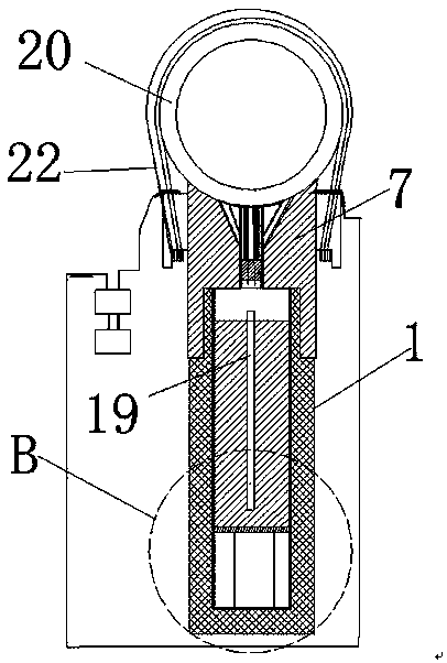
[0048] Example 3. Such as Figure 12-13 As shown, the difference between this embodiment and Embodiment 1 is that the fixing device 15 is a plurality of mounting ears provided on the top cover 7 , and each mounting ear is connected to the object 20 to be punched through a wire rope 22 . The cross section of the object 20 to be punched is rectangular. The object 20 to be punched is a metal plate.


PUM

PropertyMeasurementUnit
densityaaaaaaaaaa
densityaaaaaaaaaa
densityaaaaaaaaaa

Abstract

The invention discloses a combustion type steel component oriented cutting device. A bottom support sleeve, a top plate with a circular cross section, a cutting agent layer and an igniting agent layerare arranged in a charging barrel in sequence from bottom to top; a fixing device for fixing a top cover on objects to be punched is arranged on the radial peripheral surface of the top cover; a cylindrical through hole is formed in the center of the top cover; a cylindrical insulation plug is mounted in the through hole; the insulation plug is vertically provided with a top sleeve; two ignitionelectrodes are mounted in the center of the insulation plug, and are connected with electric ignition devices; and the top cover is provided with multiple punching holes. The cutting device is high inenergy density, high in combustion temperature, high in cutting speed and suitable for quick emergency hot cutting and underwater cutting of various steel structural parts under the conditions without electricity, gas and equipment in the fields or battlegrounds.

Description

technical field [0001] The invention relates to the field of emergency cutting, in particular to a directional cutting device for steel components. Background technique [0002] Emergency cutting is an important technology for emergency installation, repair and dismantling of field engineering facilities and equipment, and it is also an indispensable technology for army battlefield repairs. Statistics show that equipment parts are stuck, broken, perforated and other damages in the field or on the battlefield, which affect the performance of the equipment. Most of them need to be quickly solved by emergency cutting. In earthquake, snow disaster, landslide, shipwreck and other disaster rescues and daily fire rescue, there is an urgent need for a portable and safe emergency cutting method. [0003] At present, the commonly used thermal cutting methods in field repairs are plasma cutting or gas cutting. Plasma cutting is a thermal cutting method that uses high-energy density, ...

Claims


Application Information

Patent Timeline
Patent Type & Authority Applications(China)
IPC IPC(8): B23K23/00
CPCB23K23/00
Inventor 杨贵丽纪冲赵长啸谢兴博孙宇翔程良玉钟明寿李兴华
Owner ARMY ENG UNIV OF PLA
Why Eureka
Try Eureka