
Thin part machining fixture

A technology of parts processing and fixtures, which is applied in the field of fixtures for thin parts processing, can solve the problems affecting the dimensional accuracy and shape accuracy of the workpiece, the thermal deformation of the workpiece, the influence of the dimensional accuracy, shape position accuracy and surface roughness of the workpiece, etc., to achieve improvement Accuracy and qualification rate, reducing part deformation rate, ensuring quality and required effect

Pending Publication Date: 2019-04-16
上海卢宏精密机械有限公司
View PDF0 Cites 16 Cited by
  • Summary
  • Abstract
  • Description
  • Claims
  • Application Information

AI Technical Summary

Problems solved by technology

However, due to the poor rigidity and weak strength of thin parts, the thin wall of the workpiece is easy to deform under the action of clamping force during processing, which affects the dimensional accuracy and shape accuracy of the workpiece. In addition, under the action of cutting force, the workpiece will become deformed Thermal deformation, vibration deformation will also occur, affecting the dimensional accuracy, shape, position accuracy and surface roughness of the workpiece

Method used


Image

  • Thin part machining fixture
  • Thin part machining fixture
  • Thin part machining fixture

Examples


Embodiment Construction

[0019] The following will clearly and completely describe the technical solutions in the embodiments of the present invention with reference to the accompanying drawings in the embodiments of the present invention. Obviously, the described embodiments are only some, not all, embodiments of the present invention. Based on the embodiments of the present invention, all other embodiments obtained by persons of ordinary skill in the art without making creative efforts belong to the protection scope of the present invention.

[0020] In the description of the present invention, it should be noted that the orientation or positional relationship indicated by the terms "vertical", "upper", "lower", "horizontal" etc. is based on the orientation or positional relationship shown in the drawings, and is only In order to facilitate the description of the present invention and simplify the description, it does not indicate or imply that the device or element referred to must have a specific o...


PUM


Abstract

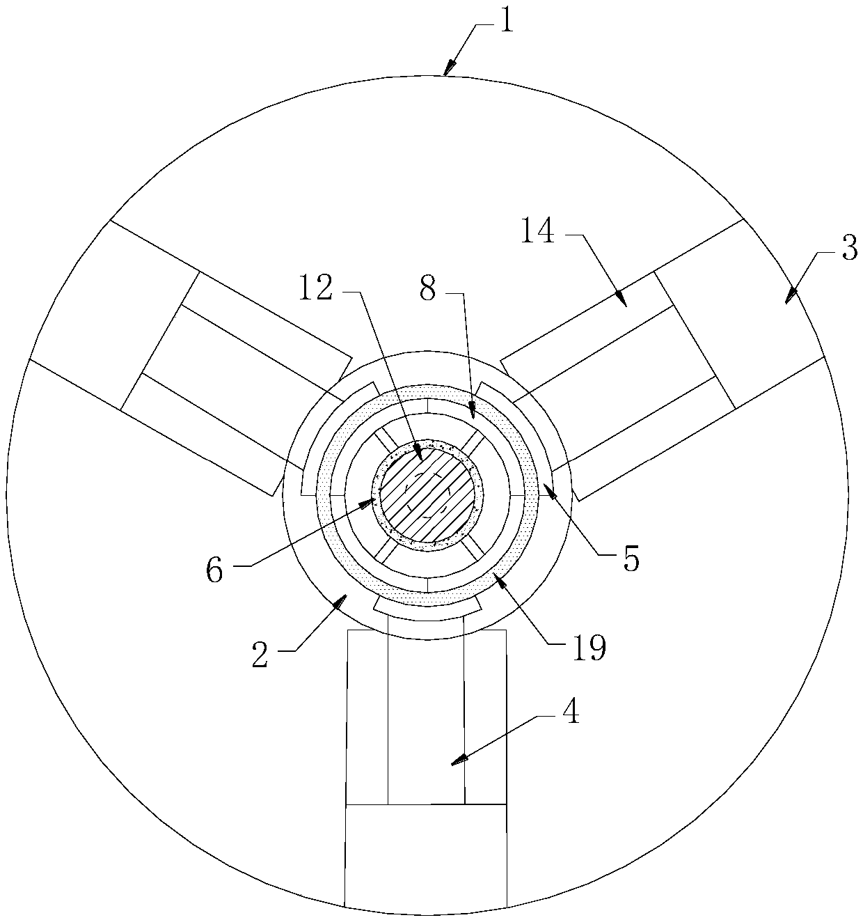
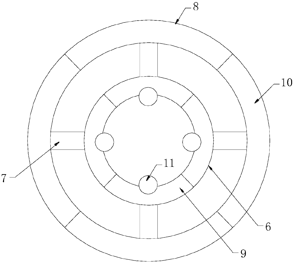
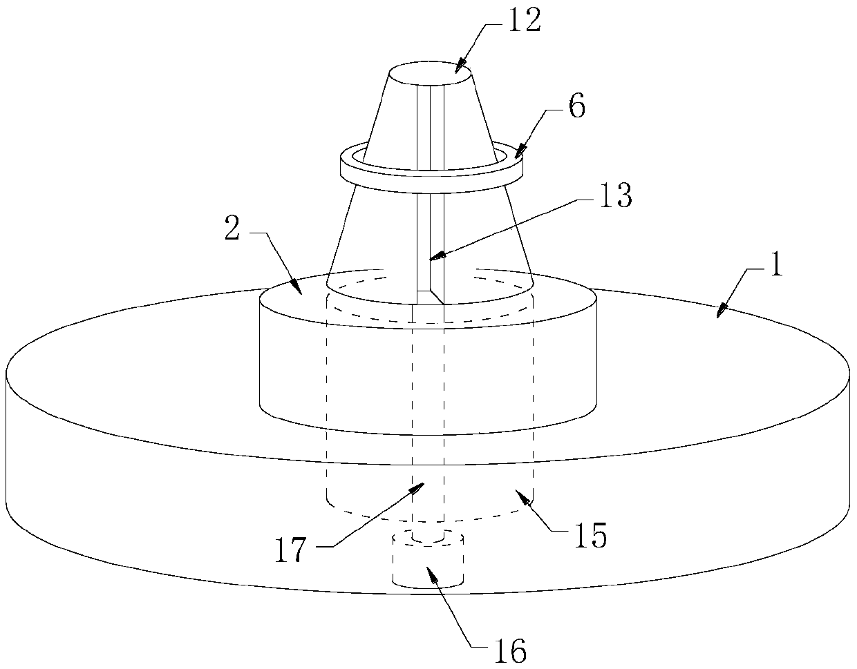
The invention discloses a thin part machining fixture. The machining fixture comprises a main base, a machining table, a plurality of external clamping mechanisms and a cylinder clamp inside support;the machining table is arranged in the center of the main base; the plurality of external clamping mechanisms are arranged on mounting seats distributed around the main base; the cylinder clamp insidesupport is arranged in the center of the machining table; each external clamping mechanism comprises an air cylinder, an extendable shaft and an external clamping curved block, wherein one end of theextendable shaft is connected with the air cylinder, and the other end of the extendable shaft is fixedly connected with the external clamping curved block; the cylinder clamp inside support includesan inner extendable ring, a connecting shaft and an inner supporting ring; the inner extendable ring is composed of a plurality of inner curved clamps; the inner supporting ring is composed of a plurality of inner support curved blocks; the number of the inner curved clamps and the number of the inner support curved blocks are equal, and each inner curved clamp and each inner support curved blockare connected into a whole through the corresponding connecting shaft; and balls are arranged on the inner side of the plurality of the inner support curved blocks in a rolling mode, and the balls are matched with ball grooves embedded in a round table type regulating mechanism.

Description

technical field [0001] The invention relates to the fields of mechanical processing and machine tool fixtures, in particular to a fixture for processing thin parts. Background technique [0002] Thin parts have the characteristics of light weight, compact structure and material saving, and are widely used in current mechanical manufacturing. However, due to the poor rigidity and weak strength of thin parts, the thin wall of the workpiece is easy to deform under the action of clamping force during processing, which affects the dimensional accuracy and shape accuracy of the workpiece. In addition, under the action of cutting force, the workpiece will change Thermal deformation and vibration deformation will also occur, affecting the dimensional accuracy, shape, position accuracy and surface roughness of the workpiece. Therefore, it is necessary to propose a fixture for processing thin parts that can solve the above problems. Contents of the invention [0003] The object of...

Claims


Application Information

Patent Timeline
IPC IPC(8): B23Q3/06
CPCB23Q3/065
Inventor 黄国林文远华张秀秀刘齐照
Owner 上海卢宏精密机械有限公司
Learn More