
Robot polishing workstation

A robot and workstation technology, applied in the field of robot polishing, can solve the problems such as the inability to meet the needs of robot polishing, the large deformation of casting blanks, and the decline of the grinding yield rate. degree of effect

Pending Publication Date: 2019-04-16
DONGGUAN ZHAOLIANG WELDING EQUIP TECH
View PDF0 Cites 5 Cited by
  • Summary
  • Abstract
  • Description
  • Claims
  • Application Information

AI Technical Summary

Problems solved by technology

[0003] Robots are used to polish stainless steel and titanium alloys with abrasive belts. The surface hardness of the workpieces is relatively high. Especially in the golf head industry, thin-walled parts below 0.8mm must be ground for grinding, and the deformation of the casting blank is relatively large. The control of the grinding force between the polishing machine and the robot, the control of the linear speed of the abrasive belt, the position control of the abrasive belt, the tension control of the abrasive belt, the deviation correction control of the abrasive belt, the weakening of the grinding force due to the wear of the abrasive belt, and sparks The control and treatment of dust protection, removal and recycling are extremely important. When traditional polishing equipment is used for polishing, the workpiece is easily deformed, and the abrasive belt and polishing wheel are worn, resulting in a decline in the grinding yield and low grinding efficiency, so that it cannot Meet the needs of robotic polishing

Method used


Image

  • Robot polishing workstation
  • Robot polishing workstation
  • Robot polishing workstation

Examples


Embodiment Construction

[0039] The following will clearly and completely describe the technical solutions in the embodiments of the present invention with reference to the accompanying drawings in the embodiments of the present invention. Obviously, the described embodiments are only some, not all, embodiments of the present invention. Based on the embodiments of the present invention, all other embodiments obtained by persons of ordinary skill in the art without making creative efforts belong to the protection scope of the present invention.

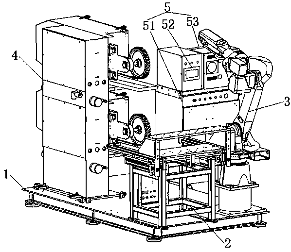
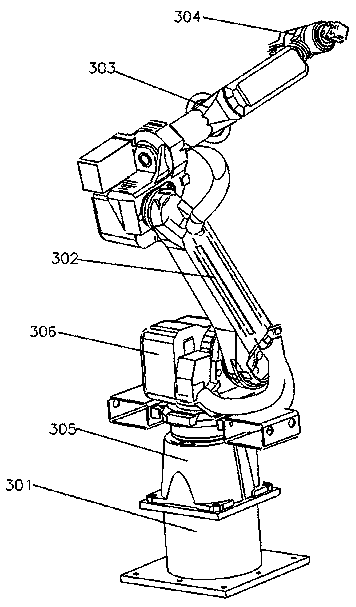
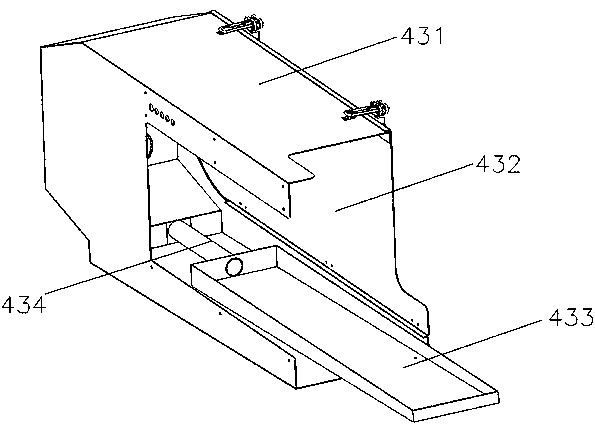
[0040] see Figure 1 to Figure 14 , an embodiment provided by the present invention: a robot polishing workstation, including a base 1, a loading and unloading table 2, a robot body 3, a polishing machine 4, and a control cabinet 5; the loading and unloading table 2 is arranged on the base 1, and the The loading and unloading platform 2 includes two first guide shaft guide rails 201 arranged in parallel, the first guide shaft guide rails 201 are fixedly connec...


PUM


Abstract

The invention discloses a robot polishing workstation. The robot polishing workstation comprises a base, an upper and lower platform component, a robot body, a polishing machine and a control cabinet,wherein the upper and lower platform component, the robot body and the polishing machine are all disposed on the base, the upper and lower platform component comprises an upper platform and a lower platform, the robot body comprises a robot big arm and a robot forearm, the polishing machine comprises a mounting plate and a vertical cabinet which is provided with at least one polishing machine module, the polishing machine modules correspond to dust suction devices one by one, and the control cabinet is connected with the upper and lower platform component, the robot body and the polishing machine. The robot polishing workstation has high automation degree and many adjustable parameters, and is provided with a spindle drive mechanism, a grinding force control mechanism, a wheel feed control feed mechanism, a belt tension adjuster, a deviation adjustment device and the dust suction devices, thereby fully meeting the grinding requirements of golf club heads and other workpieces, and remarkably avoiding the grinding yield decrease and grinding efficiency reduction caused by workpiece deformation and wear to an abrasive belt and a polishing wheel.

Description

technical field [0001] The invention relates to the technical field of robot polishing, in particular to a robot polishing workstation. Background technique [0002] With the development of science and technology, the advancement of automation technology, and the policy orientation of machine replacement, many traditional handicraft industries are facing industrial upgrading, especially in the polishing and polishing field with high operational intensity, occupational disease hazards, and a shortage of polishing professionals. Robots replace manual labor. The application of grinding and polishing is imperative. [0003] Robots are used to polish stainless steel and titanium alloys with abrasive belts. The surface hardness of the workpieces is relatively high. Especially in the golf head industry, thin-walled parts below 0.8mm must be ground for grinding, and the deformation of the casting blank is relatively large. The control of the grinding force between the polishing mac...

Claims


Application Information

Patent Timeline
Patent Type & Authority Applications(China)
IPC IPC(8): B24B21/00B24B21/18B24B21/20B24B41/00B24B47/20B24B49/16B24B55/08B24B41/06B24B41/02B25J11/00
CPCB24B21/008B24B21/18B24B21/20B24B41/005B24B41/02B24B41/06B24B47/20B24B49/16B24B55/08B25J11/0065Y02P70/10
Inventor 赵亮
Owner DONGGUAN ZHAOLIANG WELDING EQUIP TECH
Learn More