Hydraulic engineering construction device and application method thereof

A technology for construction devices and water conservancy projects, applied in cement mixing devices, clay preparation devices, chemical instruments and methods, etc., can solve the problems of insufficient mixing of materials, slowing down construction efficiency, wasting labor and time, etc. The effect of cleaning, improving mixing efficiency and improving efficiency

Inactive Publication Date: 2019-04-16
SHANGQIU JINLONG WATER CONSERVANCY ENG CO LTD
View PDF3 Cites 11 Cited by
  • Summary
  • Abstract
  • Description
  • Claims
  • Application Information

AI Technical Summary

Problems solved by technology

Concrete mixer is a machine that mixes cement, sand and gravel aggregate and water and mixes it into concrete mixture. It is mainly composed of mixing drum, feeding and unloading mechanism. The rod fully mixes cement, sand and gravel aggregates and water, so as to achieve the purpose of mixing and processing materials. The general mixers on the market fix the stirring shaft, and drive the stirring shaft to rotate through the motor, so that it is connected with the stirring shaft. The stirring rod of the mixing device moves axially to drive the mixing of the materials in the mixing tank. However, some materials in the mixing tank of this mixing device will be stuck on the inner wall of the mixing tank, so that the materials cannot be fully stirred.
The existing concrete mixers basically have the defects of low mixing efficiency and uneven mixing, which increases the mixing time and slows down the construction efficiency of the building, thus wasting a lot of labor and time of the user

Method used


Image

  • Hydraulic engineering construction device and application method thereof
  • Hydraulic engineering construction device and application method thereof
  • Hydraulic engineering construction device and application method thereof

Examples


Embodiment Construction

[0025] In order to deepen the understanding of the present invention, the present invention will be further described below in conjunction with the examples. The following examples are only used to explain the present invention, and do not constitute a limitation to the protection scope of the present invention.

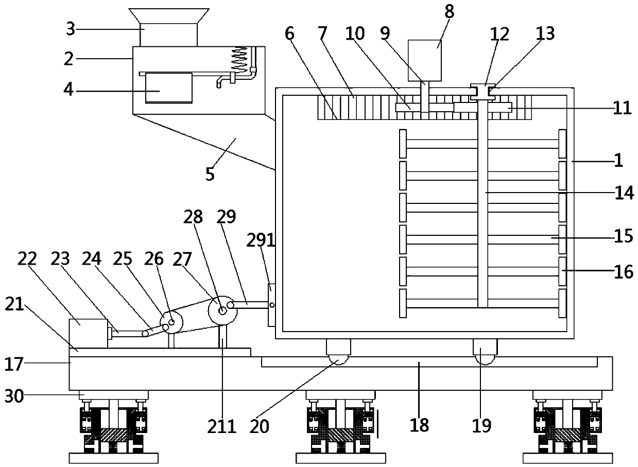
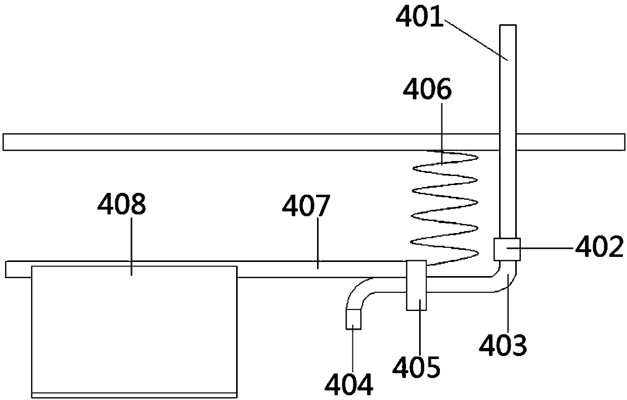
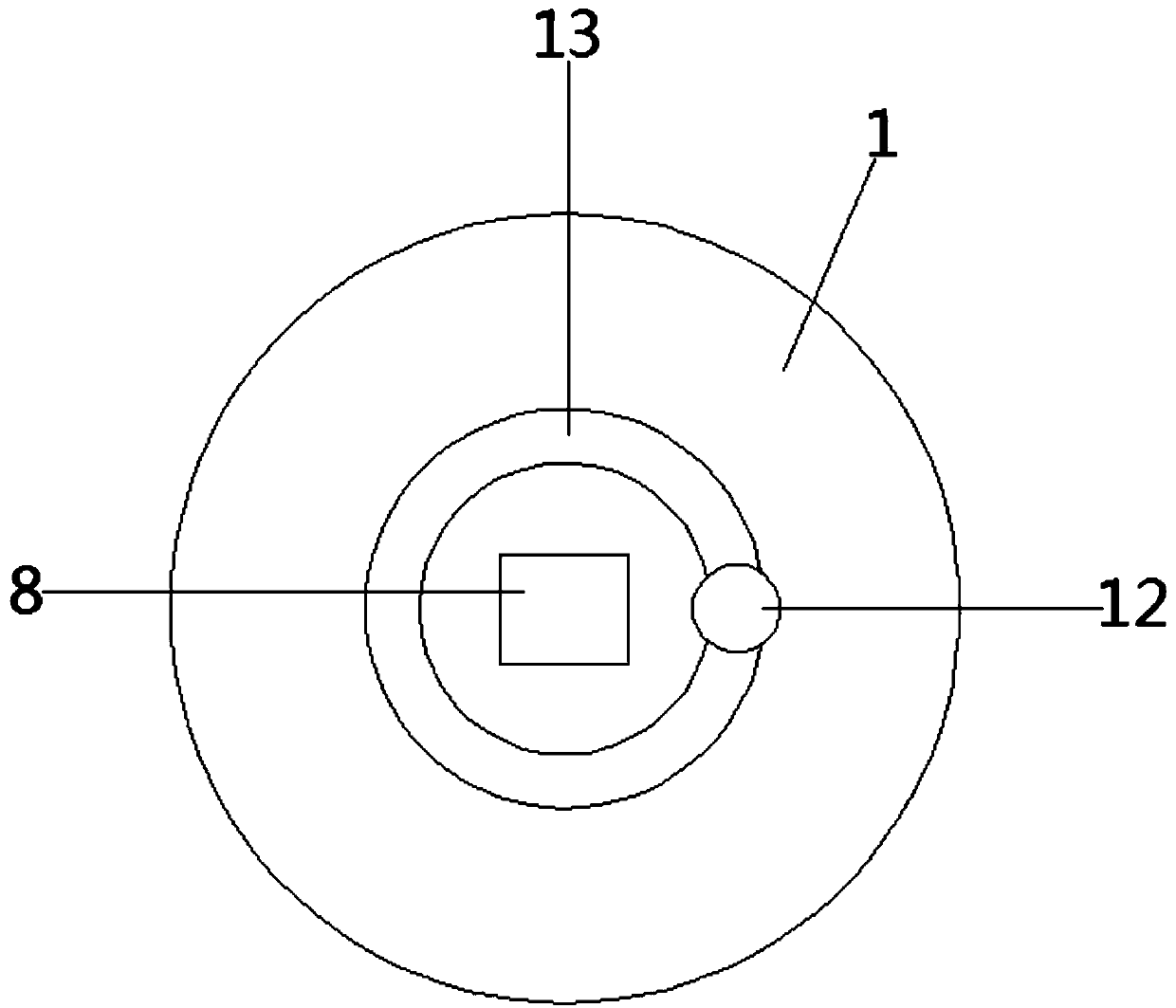
[0026] see figure 1 and figure 2 , in the embodiment of the present invention, a kind of water conservancy project construction device comprises machine body 1, and described 1 upper side left end is provided with feeding box 2, is provided with feeding hopper 3 on the upper side of feeding box 2, and feeding box 2 The bottom end of the body 1 is connected with the feeding port opened on the body 1 through the feeding pipe 5, and the body 1 is provided with a premixing device 4, which includes a fixed tube 401, a plastic elastic tube 403, a nozzle 404, a coil spring 406, Swing mechanism, one end of the fixed tube 401 is connected to the plastic elastic tube 403, th...


PUM


Abstract

The invention discloses a hydraulic engineering construction device. The hydraulic engineering construction device comprises an engine body. A feeding box is arranged at the left end of the upper side. A feeding hopper is arranged on the upper side of the feeding box. The bottom end of the feeding box is connected with a feeding port formed in the engine body through a blanking pipe. A premixing device is arranged inside the engine body. A driving motor is arranged on the upper side of the engine body. An output shaft of the driving motor penetrates through the upper surface of the engine bodyand is fixedly connected with a first gear. The invention further discloses an application method for the hydraulic engineering construction device. According to the hydraulic engineering construction device, the premixing device is arranged; the dispersing and buffering functions of a V-shaped plate are utilized, and effective premixing is conducted on raw materials and raw material additives; follow-up stirring mixing efficiency is effectively improved; on the one hand, a stirring shaft is driven to rotate by a driving motor, and on the other hand, under drive of a toothed rail, the stirring shaft conducts revolution around the axis of the engine body; stirring mixing is conducted on materials; stirring efficiency is improved greatly, and stirring is more thorough; and generation of bubbles when the materials are mixed can be effectively avoided.

Description

technical field [0001] The invention relates to the technical field of water conservancy project construction equipment, in particular to a water conservancy project construction device and a use method thereof. Background technique [0002] Water conservancy projects are projects built to control and allocate natural surface water and groundwater to achieve the purpose of eliminating harm and rejuvenating profits. Also known as water engineering. Water is an indispensable precious resource for human production and life, but its natural state does not fully meet human needs. Only by building water conservancy projects can we control water flow, prevent floods, and regulate and distribute water to meet the needs of people's life and production for water resources. Water conservancy projects need to build different types of hydraulic structures such as dams, dikes, spillways, sluices, water inlets, channels, canals, rafts, and fishways to achieve their goals. [0003] The c...

Claims


Application Information

Patent Timeline
Patent Type & Authority Applications(China)
IPC IPC(8): B28C5/16B28C5/08B28C7/06B28C5/02
CPCB28C5/026B28C5/0806B28C5/0856B28C5/0875B28C5/16B28C7/067
Inventor 刘亚坤杜贝贝王梦帆程艳华郭东波段刘勇贺凡任永生
Owner SHANGQIU JINLONG WATER CONSERVANCY ENG CO LTD
Why Eureka
Try Eureka