
Integrated rotation seal system

A rotary sealing, one-piece technology, applied in clay preparation devices, chemical instruments and methods, cement mixing devices, etc., can solve the problems of high production and use costs, high replacement costs, blocking failures, etc., and achieve low maintenance costs. The effect of low maintenance and blockage avoidance

Pending Publication Date: 2019-04-16
YANTAI SHENGLIDA ENG TECH
View PDF1 Cites 9 Cited by
  • Summary
  • Abstract
  • Description
  • Claims
  • Application Information

AI Technical Summary

Problems solved by technology

[0002] The mixing drum of the traditional concrete mixer truck is open, which has many disadvantages such as poor weather resistance and driving safety, easy spillage, and poor passability.
In 2010, the applicant proposed to invent the "Rotary Sealing Device for Mixing Drum of Concrete Mixer Truck", which solved the above problems in one fell swoop, but also brought problems such as heavy weight of the device, large amount of maintenance, many wearing parts, and high replacement costs.
[0003] The patent "Hollow Shaft Rotary Sealed Concrete Mixer Truck" applied on August 29, 2017, with the announcement number CN107344401A, solved the above problems, but because of its rolling contact fit, it brought new problems: 1. Under the action of frequent working pressure cycles, the bolt holes are easy to leak mud into the interior of the slewing support, causing its resistance to increase until the blockage fails; 2. Too many bolts make loading and unloading complicated; 3. The weight of the device is large; 4. The replacement cost of spare parts is relatively higher
For the slewing support with sliding contact, there are: 1. The bolt holes are easy to enter the sediment and cause serious wear; 2. The lubricating oil is not easy to add, and dry grinding occurs, resulting in serious wear; Complex maintenance; 4. Both production cost and use cost are high

Method used


Image

  • Integrated rotation seal system
  • Integrated rotation seal system

Examples


Embodiment Construction

[0022] The technical scheme of the present invention is described in detail below in conjunction with accompanying drawing:

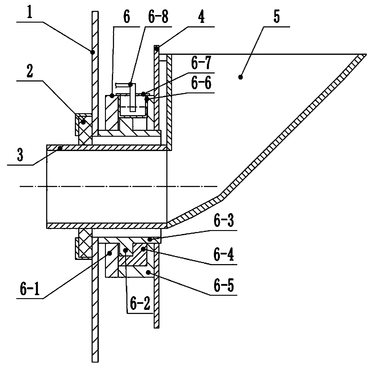
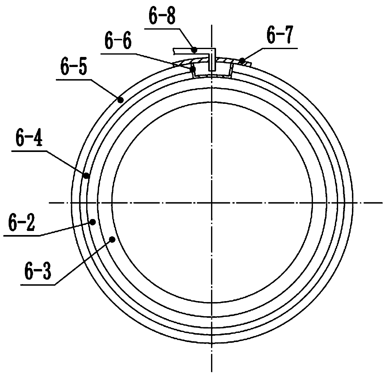
[0023] Such as figure 1 and 2 , an integrated rotary sealing system, used for the rotary sealing of the mixing drum of the mixer truck.

[0024] The mixer truck includes a car body and the mixing drum installed on the car body, and also includes a revolving cover 1, a central hole is provided on the revolving cover 1, and the outer circle of the revolving cover 1 is in contact with the mixing drum to follow the rotation of the mixing drum; it also includes a mobile frame 4 movably installed on the vehicle frame and a driving device for driving the mobile frame 4 to move relative to the vehicle body. A combined rotary support device 6 is also provided. The rotary cover 1 is installed on the mobile frame 4 through the combined rotary support device 6. On the one hand, it moves with the mobile frame 4, and on the other hand, it will rotate with the mixin...


PUM


Abstract

The invention discloses an integrated rotation seal system. The integrated rotation seal system comprises a rotation cover, a rotation barrel, a rotation support, a moving frame, a feeding hopper, a discharging barrel and the like. The rotation cover is arranged on the moving frame through a combined rotation support device. The combined rotation support device comprises a rotation barrel, and a rotation track is arranged on the outer cylinder face of the rotation barrel. A front ring and a rear ring which are connected are included. A track groove used for being matched with the rotation track is formed in the inner circle face position of the front end face of the rear ring. An abrasion ring is arranged in the rear ring, and the rear ring and the front ring can move forwards along with abrasion of the abrasion ring. The top of the rear ring is provided with a lubrication cavity for containing a lubricating agent. The part, making contact with the rotation track in a matched manner, of the track groove communicates with the lubrication cavity. By means of the integrated rotation seal system, the manufacturing cost and the maintaining workload and cost of the rotation support are reduced, and meanwhile sediments can be prevented from entering the rotation support.

Description

technical field [0001] The invention relates to an integrated rotary sealing system for a mixer truck. Background technique [0002] The mixing drum of the traditional concrete mixer truck is open, which has many disadvantages such as poor weather resistance and driving safety, easy spillage, and poor passability. In 2010, the applicant proposed to invent the "Rotary Sealing Device for Mixing Drum of Concrete Mixer Truck", which solved the above problems at one stroke, but also brought problems such as heavy device weight, large maintenance, many wearing parts, and high replacement costs. [0003] The patent "Hollow Shaft Rotary Sealed Concrete Mixer Truck" applied on August 29, 2017, with the announcement number CN107344401A, solved the above problems, but because of its rolling contact fit, it brought new problems: 1. Under the action of frequent working pressure cycles, the bolt holes are easy to leak mud into the interior of the slewing support, causing its resistance t...

Claims


Application Information

Patent Timeline
IPC IPC(8): B28C5/42
CPCB28C5/4262
Inventor 盛富春盛镝盛楠
Owner YANTAI SHENGLIDA ENG TECH
Learn More