A mobile garbage compression equipment with electromechanical and hydraulic integration

A garbage compression and mobile technology, which is applied in the direction of garbage collection, garbage transmission, loading/unloading, etc., can solve the problems of high force requirements for structural parts, high operating costs, and unsatisfactory performance, so as to improve environmental protection and work efficiency. Reduce floor space and improve extrusion efficiency

Active Publication Date: 2022-03-29
YIWU INDAL & COMMERICAL COLLEGE
View PDF7 Cites 0 Cited by
  • Summary
  • Abstract
  • Description
  • Claims
  • Application Information

AI Technical Summary

Problems solved by technology

[0003] However, garbage is usually compressed during transportation and treatment, and in the field of garbage compression, horizontal direct-pressure compressors are usually used, but this type of compressor is less economical in transfer: garbage bins and matching pull-arm garbage The transfer vehicle is heavy and has a low payload
Poor adaptability, difficulty in unloading garbage bins in frozen areas and large rebound garbage; poor environmental protection in transshipment: it is difficult to control the leakage of sewage from the discharge door at the end of the garbage bin
[0004] In view of the problems existing in the above-mentioned technologies, a horizontal pre-compressed garbage compressor has been implemented in the prior art, but this kind of compressor has a long length, high requirements on the force of the structural parts, heavy equipment, high equipment cost, and a large floor area. With high compression force and high specific pressure to compress garbage, large diameter hydraulic cylinder, high power motor and large displacement hydraulic pump, the cost is high and the operating cost is high; under high compression force, the compression stability of a single cylinder is poor, so that the volume of the pre-compressed garbage block is affected. limit, unable to meet the requirements of a 31-ton transfer vehicle for loading briquettes at one time

Method used


Image

  • A mobile garbage compression equipment with electromechanical and hydraulic integration
  • A mobile garbage compression equipment with electromechanical and hydraulic integration

Examples


Embodiment Construction

[0023] The following is further described in detail through specific implementation methods:

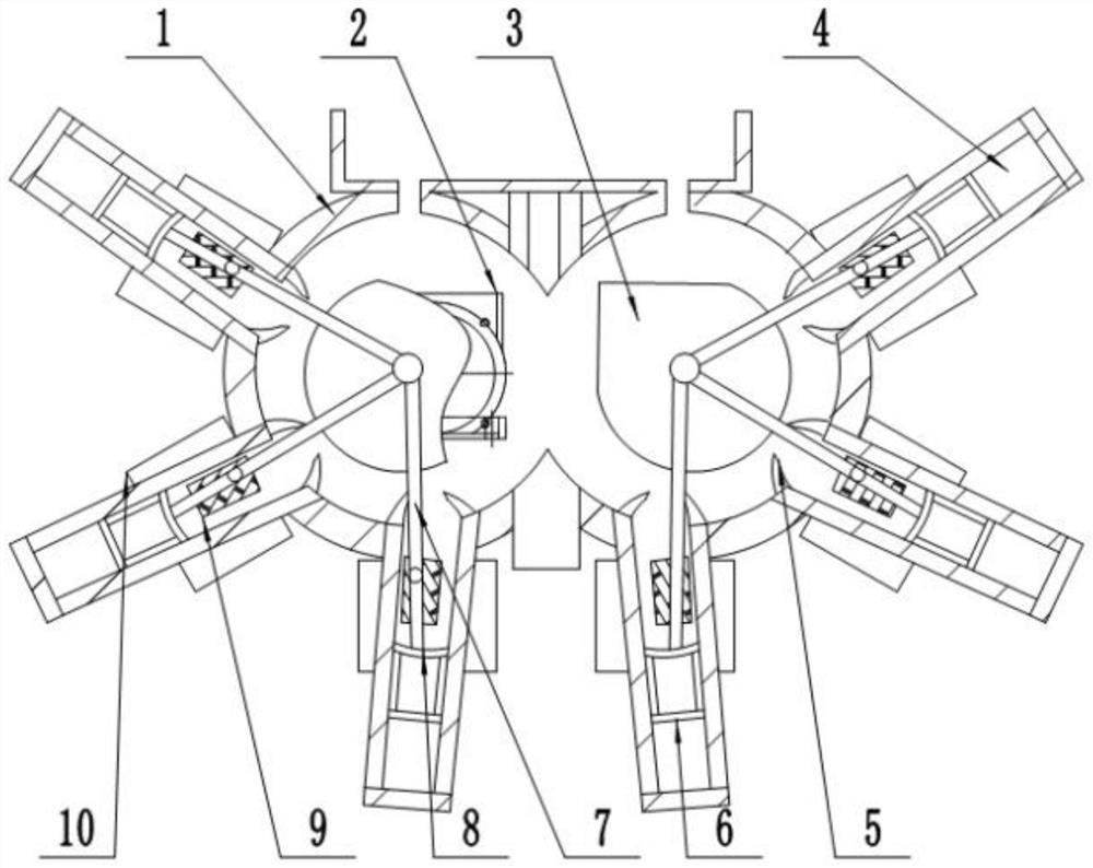
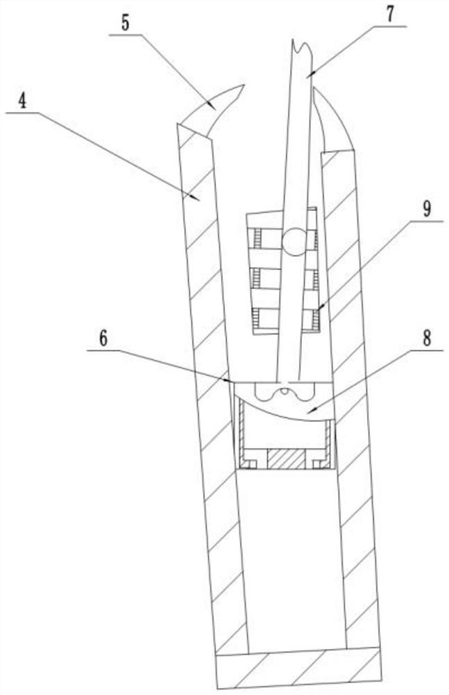
[0024] The reference signs in the drawings of the specification include: compression box 1, drive motor 2, rotor 3, waste liquid treatment channel 4, lug 5, piston 6, connecting rod group 7, groove 8, discharge port 9, water storage tank 10.

[0025] The embodiment is basically as attached figure 1 Shown: a mobile garbage compression equipment with electromechanical and hydraulic integration, including a compression box 1 and a drive motor 2, two mutually symmetrical elliptical rotors 3 are installed in the compression box 1, and the rotor 3 is driven by the drive motor 2, A group of waste liquid treatment channels 4 symmetrically arranged along the central axis of the compression box 1 is formed on the circumference of the rotor 3. The waste liquid treatment channels 4 are radially arranged, and the number of waste liquid treatment channels 4 is 6. The waste liquid treatment channe...


PUM


Abstract

The invention discloses an electromechanical-hydraulic integrated mobile garbage compression equipment in the field of garbage treatment. This equipment includes a compression box, which is provided with two mutually symmetrical elliptical rotors, the rotors are connected with a drive motor, and a set of waste liquid treatment channels symmetrical along the central axis of the compression box are provided on the circumference of the rotors. The waste liquid treatment channels are radially arranged, and the number of waste liquid treatment channels is at least 6. Pistons are slidably connected in the waste liquid treatment channels, and a connecting rod group is connected between the pistons and the rotor. During the stroke of the pistons, There is a discharge port, and the discharge port is axially arranged in the waste liquid treatment channel. The device has a compact structure, and at the same time, the sewage in the garbage is introduced into the waste liquid treatment channel by the piston, which avoids sewage discharge at the tail of the device, and improves environmental protection and work efficiency.

Description

technical field [0001] The invention relates to the field of garbage disposal, in particular to a mobile garbage compression equipment with electromechanical and hydraulic integration. Background technique [0002] Pollution caused by domestic waste has always been one of the most serious public hazards in China. Especially in recent years, with the rapid development of the regional economy, the garbage in public places cannot be collected better, and the problems of garbage polluting the environment and affecting the appearance of the city are becoming more and more serious. Therefore, collecting and treating garbage well, preventing environmental pollution, protecting the environment, maintaining ecological balance and creating a good city appearance have become important measures for social development, and it is also the obligation of every citizen. [0003] However, garbage is usually compressed during transportation and treatment, and in the field of garbage compressi...

Claims


Application Information

Patent Timeline
Patent Type & Authority Patents(China)
IPC IPC(8): B65F9/00
CPCB65F9/00
Inventor 朱永强
Owner YIWU INDAL & COMMERICAL COLLEGE
Why Eureka
Try Eureka