Eddy current machine nickel-iron alloy magnetic conductive plate and manufacturing method thereof

A production method and ferroalloy technology, applied in the field of powder metallurgy of metal materials, can solve the problems of increasing the ampere-turns of electric coils, increasing material costs, and small braking torques, so as to reduce the ampere-turns of coils, reduce production costs, and lead good magnetic effect

Inactive Publication Date: 2019-04-16
浙江江兴汽车检测设备有限公司
View PDF13 Cites 1 Cited by
  • Summary
  • Abstract
  • Description
  • Claims
  • Application Information

AI Technical Summary

Problems solved by technology

[0003] The exciter core and magnetic plate of modern eddy current machines are usually made of iron with low magnetic permeability or pure electrical iron. Due to the limitation of magnetic permeability, the number of ampere turns of the electric coil can only be increased, thus increasing the cost of materials, or manufacturing The power torque is too small to meet the demand

Method used


Image

  • Eddy current machine nickel-iron alloy magnetic conductive plate and manufacturing method thereof
  • Eddy current machine nickel-iron alloy magnetic conductive plate and manufacturing method thereof

Examples


Embodiment 1

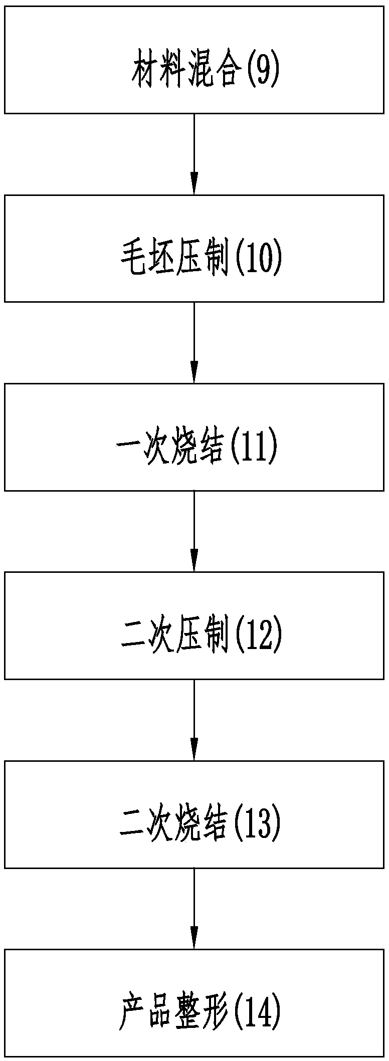
[0042] Step 1. Mix 4.9% carbonyl nickel powder, 0.6% microwax powder, 0.4% manganese sulfide and 94.1% pure iron powder in proportion by weight, wherein carbonyl nickel powder is selected from 200 mesh carbonyl nickel powder, and pure iron powder is selected from 100 mesh Water atomized pure iron powder.

[0043] Step 2. Put the mixed raw materials into the blank mold cavity, press 6.3 g / cm 3 The density is pressed to make a blank.

[0044] Step 3: The blank is sintered for the first time at a temperature of 1050° C. under a protective atmosphere mixed with nitrogen and hydrogen to obtain a product.

[0045] Step 4. After the first sintering is completed, the product is pressed at 7.46 g / cm 3 The density is double-compressed to make the product have a higher material density.

[0046] Step 5, the product is sintered for the second time at a temperature of 1180° C. under a mixed protective atmosphere of nitrogen and hydrogen.

[0047] Step 6: After the second sintering is c...

Embodiment 2

[0050]Step 1. Mix 5% carbonyl nickel powder, 0.5% microwax powder, 0.5% manganese sulfide and 94% pure iron powder in proportion by weight, wherein carbonyl nickel powder is selected from 200 mesh carbonyl nickel powder, and pure iron powder is selected from 100 mesh Water atomized pure iron powder.

[0051] Step 2: Put the mixed raw materials into the blank mold cavity, press 6.2 g / cm 3 The density is pressed to make a blank.

[0052] Step 3: The blank is sintered for the first time at a temperature of 1050° C. under a protective atmosphere mixed with nitrogen and hydrogen to obtain a product.

[0053] Step 4. After the first sintering is completed, the product is pressed at 7.42 g / cm 3 The density is double-compressed to make the product have a higher material density.

[0054] Step 5, the product is sintered for the second time at a temperature of 1180° C. under a mixed protective atmosphere of nitrogen and hydrogen.

[0055] Step 6: After the second sintering is comple...


PUM

PropertyMeasurementUnit
densityaaaaaaaaaa
tensile strengthaaaaaaaaaa
densityaaaaaaaaaa

Abstract

The invention discloses an eddy current machine nickel-iron alloy magnetic conductive plate and a manufacturing method thereof, and the technical scheme thereof comprises the following steps: mixing nickel carbonyl powder, micro wax powder, manganese sulfide and pure iron powder in proportion, wherein the mass percents of nickel carbonyl powder, micro wax powder, manganese sulfide, and pure iron powder are 3.5-5%, 0.5-0.6%, 0.4-0.5%, and 94-95.5%, respectively; loading the mixed raw material into a blank cavity according to the design component, and pressing to obtain a blank; sintering the blank firstly under a mixed protective atmosphere of nitrogen and hydrogen to obtain a product; after the first sintering is completed out of a furnace, second re-pressing is carried out on the product;sintering the product secondly under a mixed protective atmosphere of nitrogen and hydrogen; and after the second sintering is completed, shaping and deburring the product. The invention has the effects of high production efficiency, good magnetic permeability, fast heat dissipation, stable electromagnetic force of a magnetic field and low production cost.

Description

technical field [0001] The invention relates to the technical field of metal material powder metallurgy, in particular to a nickel-iron alloy magnetic conducting plate of an eddy current machine and a manufacturing method thereof. Background technique [0002] At present, the eddy current machine designed at home and abroad usually consists of frame 1, excitation winding 5, excitation core 2, magnetic guide plate 7, eddy current rotor 3, rotating shaft 6, bearing 4, insulating frame 8, junction box and so on. Such as figure 1 As shown, when the excitation winding 5 is powered on, a closed magnetic flux is generated around the excitation winding 5 , and the eddy current rotor 3 rotates with the rotating shaft 6 . The eddy current rotor 3 cuts the magnetic field lines generated by the field core 2 , so that a vortex-shaped induced current is generated inside the eddy current rotor 3 . In this way, the excitation core 2 and the magnetic guide plate 7 will apply an electromagn...

Claims


Application Information

Patent Timeline
Patent Type & Authority Applications(China)
IPC IPC(8): C22C38/08C22C38/04C22C38/60C22C33/02B22F3/16
CPCB22F3/16C22C33/0264C22C38/04C22C38/08C22C38/60
Inventor 徐益东刘元鹏朱清陈龙水
Owner 浙江江兴汽车检测设备有限公司
Why Eureka
Try Eureka