

Tunnel two-lining concrete pouring system
A concrete and tunnel technology, which is applied in the direction of tunnel lining, tunnel, shaft lining, etc., can solve the problems of arch concrete artificiality, small vibration radius, concrete voids, etc., to solve the problem of uncompacted concrete, ensure construction quality, and meet construction needs Effect
- Summary
- Abstract
- Description
- Claims
- Application Information
AI Technical Summary
Problems solved by technology
Method used
Image

Examples
Embodiment Construction
[0044] The present invention will be further described in detail below in conjunction with the accompanying drawings and specific embodiments.
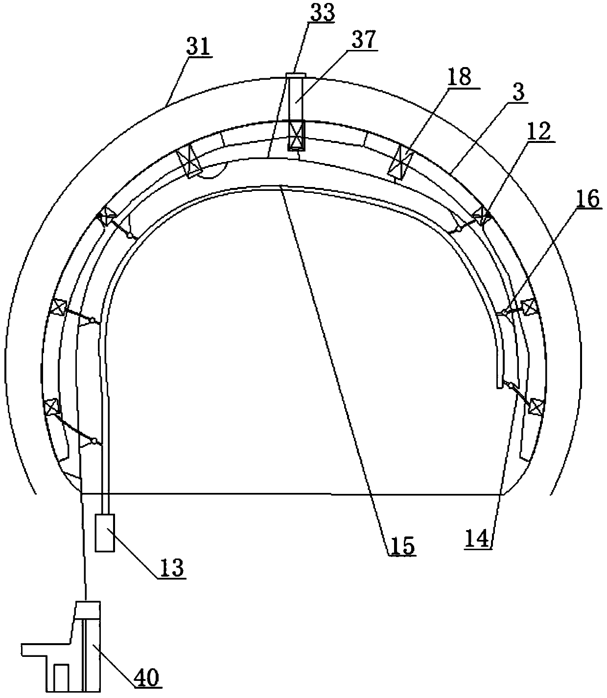
[0045] see figure 1 , The concrete pouring system for the second lining of the tunnel, including a flow monitoring device, a mold entry temperature monitoring device, a pressure visualization soft-lapping device, a plurality of high-frequency pneumatic vibrators 12, a gas compressor 13 and an electric control box 40.
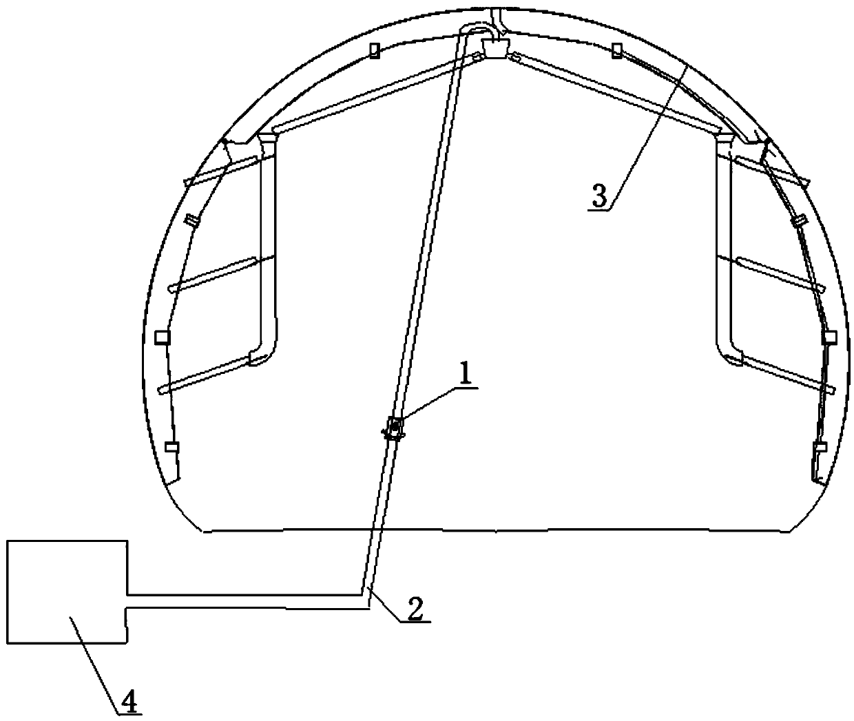
[0046] see figure 2 , the flow monitoring device includes a three-dimensional laser scanner and a flow sensor 1, and the flow sensor 1 is installed on the concrete main delivery pump pipe 2; all the concrete entering the second lining is transported through the concrete main delivery pump pipe 2, and the flow rate The sensor 1 records the volume of concrete passing through the concrete main delivery pump pipe 2. The three-dimensional laser scanner and the flow sensor meter 1 are all connected to the electric control ...
PUM
| Property | Measurement | Unit |
|---|---|---|
| Circumferential spacing | aaaaa | aaaaa |
Abstract
Description
Claims
Application Information