
Solid rocket super combustion ramjet engine, arc-shaped fuel gas generator and center injection device

A gas generator and scramjet technology, which is applied in rocket engine devices, ramjet engines, combined engines, etc., can solve the problem of reducing the size of solid rocket scramjet engines, reducing the difficulty of thermal protection on the engine wall, and inefficient use of engine space. Reasonable and other issues to achieve the effect of improving volume utilization, avoiding excessive aspect ratio and reducing total length

Active Publication Date: 2019-04-16
NAT UNIV OF DEFENSE TECH
View PDF7 Cites 6 Cited by
  • Summary
  • Abstract
  • Description
  • Claims
  • Application Information

AI Technical Summary

Problems solved by technology

[0005] The invention provides a solid rocket scramjet engine, an arc-shaped gas generator, and a central injection device, which are used to overcome defects such as unreasonable utilization of engine space, low filling ratio, and difficulty in thermal protection in the prior art, and realize the integration of the engine space. Reasonable use, increase the filling ratio, reduce the size of the solid rocket scramjet, realize its long-distance flight function, and improve the mixing and combustion efficiency of the engine, and reduce the difficulty of thermal protection of the engine wall

Method used


Image

  • Solid rocket super combustion ramjet engine, arc-shaped fuel gas generator and center injection device
  • Solid rocket super combustion ramjet engine, arc-shaped fuel gas generator and center injection device
  • Solid rocket super combustion ramjet engine, arc-shaped fuel gas generator and center injection device

Examples


Embodiment 1

[0051] Please refer to figure 1 , the present embodiment provides a solid rocket scramjet, an arc-shaped gas generator, and a central injection device,

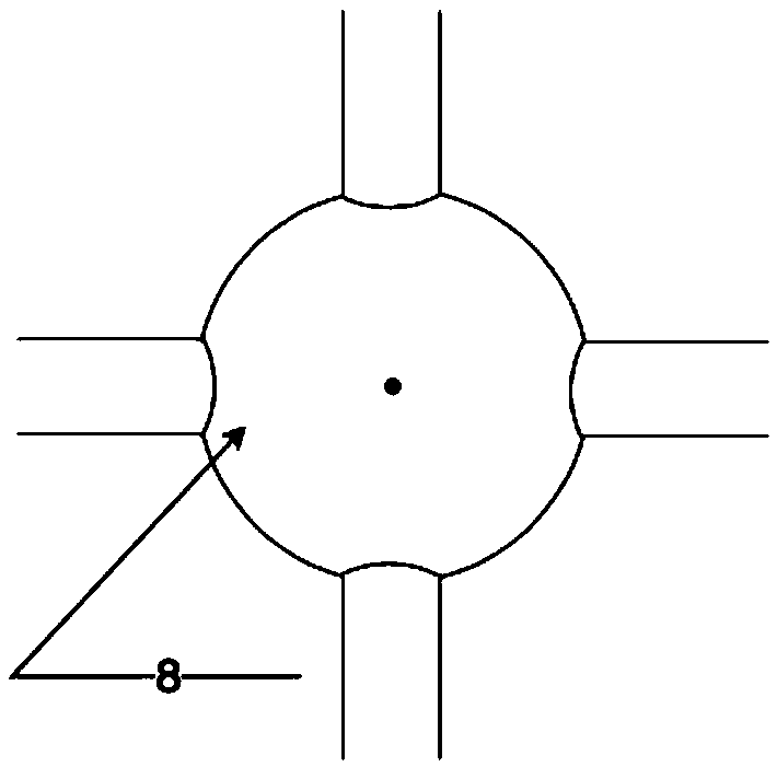
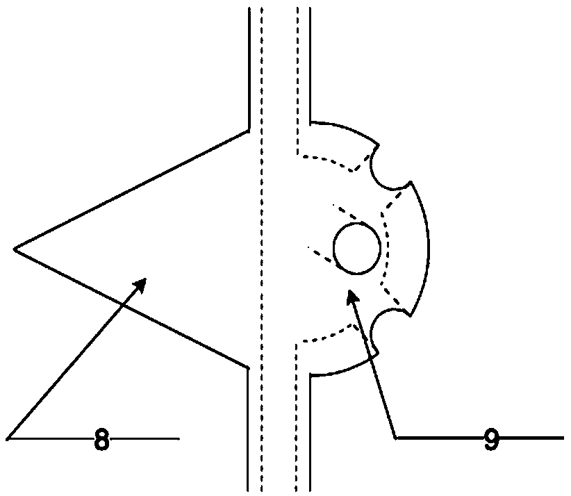
[0052] The solid rocket scramjet comprises a precursor 7, an air inlet 4, a supplementary combustion chamber 3, a tail nozzle 5, a gas generator 2 with a radian of 2π and fixedly surrounding the supplementary combustion chamber 3, four The guide pipe 6 arranged on the axial direction of the gas generator 2 near the end of the air inlet 4 is symmetrical to the center;

[0053] The gas generator 2 is cylindrical and has a cavity capable of containing solid propellant, and the size of the cavity can fully load the required amount of solid propellant 1;

[0054] The guide pipe 6 includes an injection device arranged at the nozzle end, and the nozzle end is arranged perpendicular to the flow direction of the incoming air; the injection device is located between the afterburning chamber 3 and the air intake channel 4, And the cen...

Embodiment 2

[0057] Please refer to image 3 , the present embodiment provides a solid rocket scramjet, an arc-shaped gas generator, and a central injection device,

[0058] The solid rocket scramjet engine comprises a precursor 7, an air inlet 4, an afterburner 3, a tail nozzle 5, and three arcs of 2π are respectively fixed and surround the afterburner 3, the air inlet 4, and the tail The gas generator 2 on the nozzle 5, each gas generator 2 is provided with two guide tubes 6 near the end of the air inlet 4 in the axial direction, and the two guide tubes 6 are center-symmetrically distributed on the end face;

[0059] The gas generator 2 is cylindrical and has a housing chamber capable of holding solid propellant, and the total volume of the three housing chambers can be fully loaded with the required amount of solid propellant 1;

[0060] The guide tube 6 includes an injection device arranged at the nozzle end, and the nozzle end of the guide tube 6 fixedly surrounding the gas generator...

Embodiment 3

[0064] Please refer to Figure 5 , the present embodiment provides a solid rocket scramjet, an arc-shaped gas generator, and a central injection device,

[0065] The solid rocket scramjet engine includes a precursor 7, an air inlet 4, a supplementary combustion chamber 3, an exhaust nozzle 5, and two arcs of 2π, which are respectively fixedly installed inside the precursor 7 and fixedly surrounded in the supplementary combustion chamber 3 on the gas generator 2; the gas generator 2 inside the precursor 7 is only provided with a guide tube 6, and the guide tube 6 is arranged at the end of the gas generator 2 near the air inlet 4, and its nozzle end is parallel to the incoming air The flow direction is such that the fuel-rich gas enters the supplementary combustion chamber 3 and is parallel to the incoming air; the gas generator 2 fixed around the supplementary combustion chamber 3 is provided with four guide tubes 6, and the four guide tubes 6 are centrally symmetrical Distrib...


PUM


Abstract

The invention discloses a solid rocket super combustion ramjet engine, an arc-shaped fuel gas generator and a center injection device. The engine comprises a front body, a gas input channel, a fuel supplementing chamber, a tail injection pipe, at least one fuel gas generator and at least one flow guide pipe. The fuel gas generator is of an arc shape, is provided with a containing cavity capable ofcontaining solid propellant, and is fixedly assembled on the fuel supplementing chamber or the gas input channel or the tail injection pipe as a whole or in a subsection manner in the direction parallel to the axial direction of the fuel supplementing chamber, or arranged in the front body. An injection device of the flow guide pipe is located between the fuel supplementing chamber and the gas input channel. A flow guide cone is arranged at the end, close to the gas input channel, of the injection device, and a mixing reinforcement structure is arranged at the end, close to the fuel supplementing chamber, of the injection device. Compared with an existing solid rocket sub combustion ramjet engine and super combustion ramjet engine, the engine is reasonable in space application, the filling ratio is increased, the size of the engine is reduced, the long-range flying function of the engine can be achieved, and meanwhile, the heat protection pressure of the engine is effectively reduced.

Description

technical field [0001] The invention relates to the technical field of solid rocket scramjet, in particular to a solid rocket scramjet, an arc-shaped gas generator, and a central injection device. Background technique [0002] The solid rocket scramjet is the power plant of the hypersonic vehicle, and the structural design of the grain is one of the key technologies of the solid rocket scramjet. In the decades of engineering applications of solid rocket motors, a large number of related design technologies have been accumulated. [0003] The charging method of the existing solid rocket sub-combustion ramjet mostly assembles the solid propellant at the front side of the gas generator. The solid propellant burns along the axial direction and injects rich fuel gas. Incoming air mixed combustion. Since the working Mach number of the solid rocket sub-combustion ramjet engine is not high, generally not more than 4, the incoming air will become subsonic after being compressed by ...

Claims


Application Information

Patent Timeline
Patent Type & Authority Applications(China)
IPC IPC(8): F02K7/18F02K9/24F02K9/32
CPCF02K7/18F02K9/24F02K9/32
Inventor 马立坤赵翔夏智勋刘冰李潮隆王德全王林
Owner NAT UNIV OF DEFENSE TECH
Learn More