Irregular part detection and positioning method

A positioning method and irregular technology, applied in the field of visual inspection, can solve the problems of affecting the operation efficiency and operation quality of visual inspection equipment, unfavorable routine changes of parameters, high use cost, etc., to overcome the influence of ambient light, control the manufacturing use cost, The effect of improving the efficiency of use

Inactive Publication Date: 2019-04-16
东莞中科蓝海智能视觉科技有限公司
View PDF3 Cites 3 Cited by
  • Summary
  • Abstract
  • Description
  • Claims
  • Application Information

AI Technical Summary

Problems solved by technology

[0003] As mentioned above, visual inspection has a huge market value. The core of the visual inspection system is not the hardware equipment but the algorithm steps, and the algorithm steps will vary depending on the requirements of the inspection results, product shape, working environment, and the technology of the designer or group. Factors such as capabilities vary widely. If the design of the core algorithm steps is lacking, it will affect the operating efficiency and quality of the entire set of visual inspection equipment. In the algorithm steps of irregular parts detection and positioning, most of the technical solutions on the market are expensive to use, and at the same time The algorithm steps are also relatively complicated, which is not conducive to the general technical staff's routine parameter change and other operation settings

Method used


Image

  • Irregular part detection and positioning method
  • Irregular part detection and positioning method
  • Irregular part detection and positioning method

Examples


Embodiment Construction

[0023] In order to facilitate the understanding of those skilled in the art, the present invention will be further described below in conjunction with the examples, and the contents mentioned in the embodiments are not intended to limit the present invention.

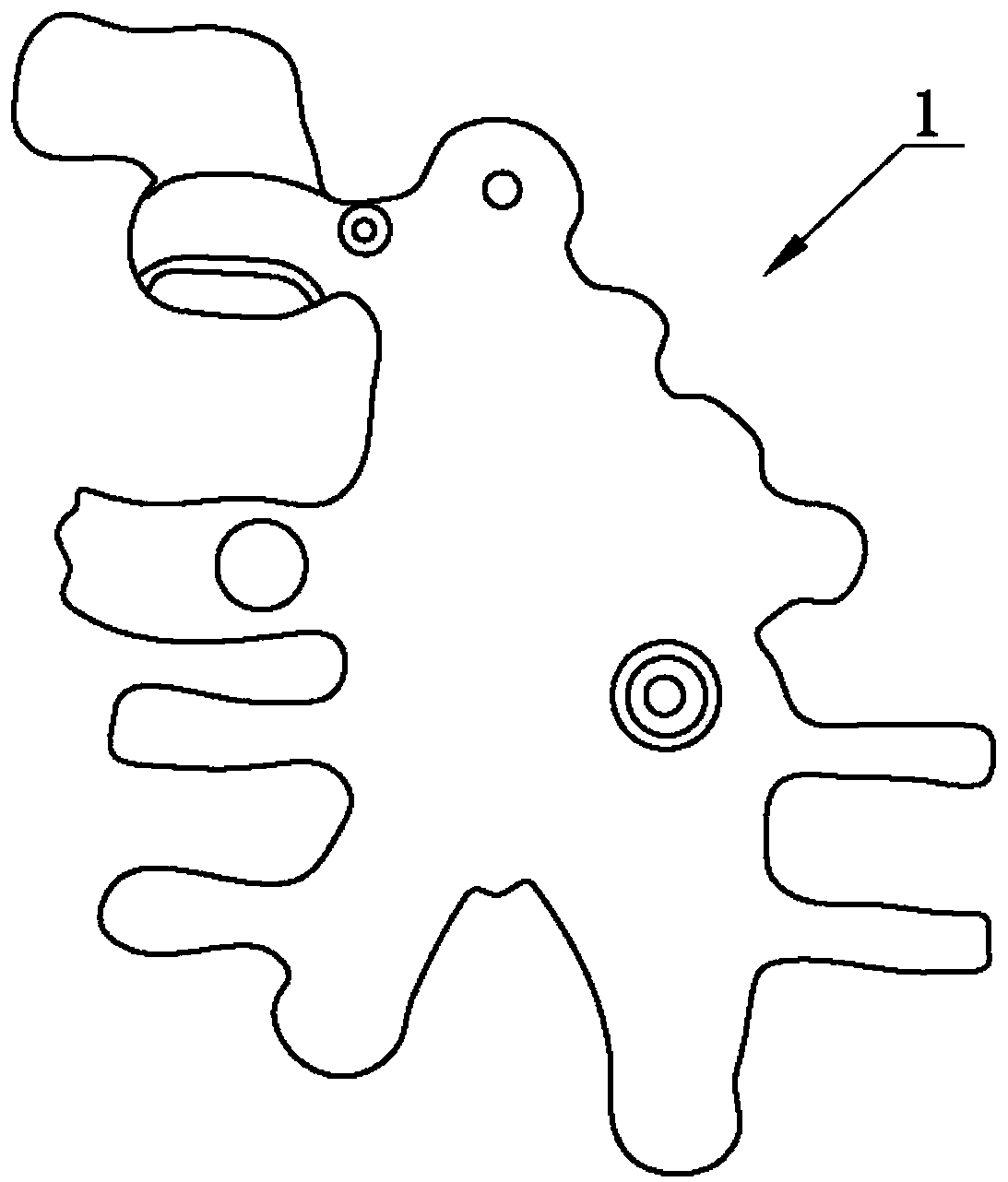
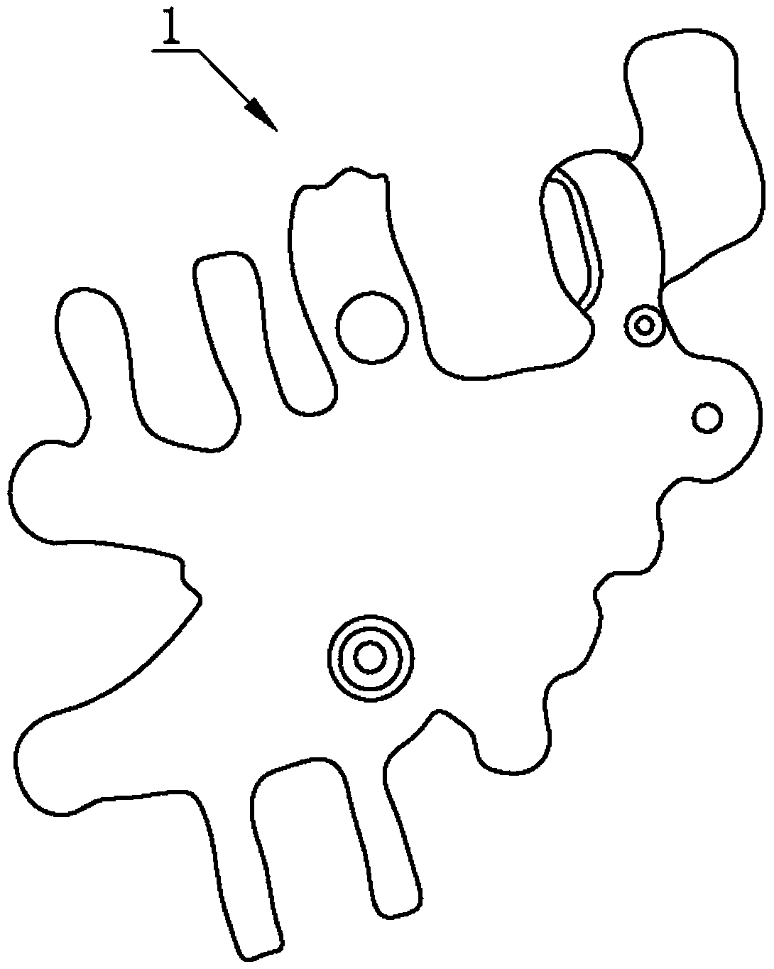
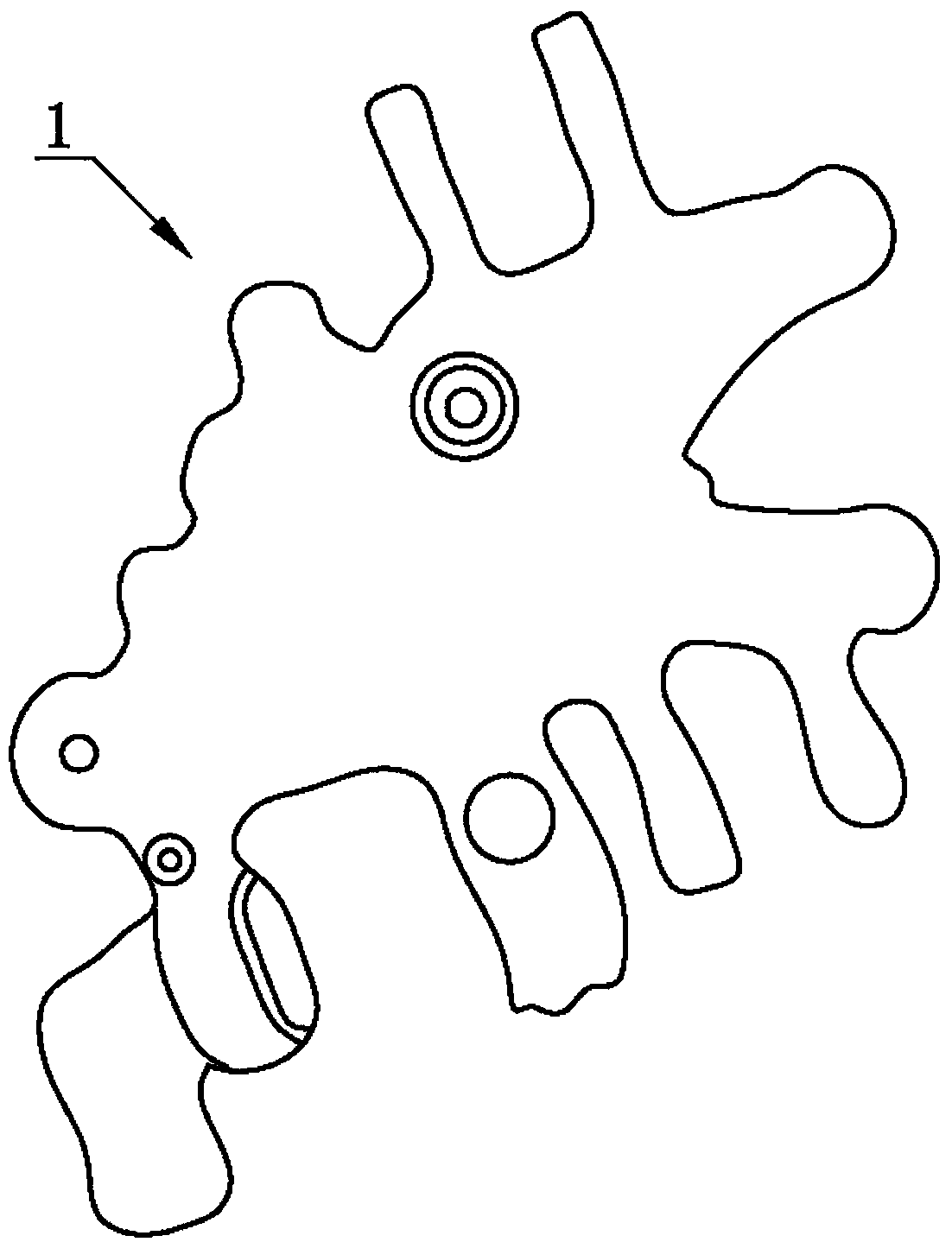
[0024] Such as Figure 1 to Figure 3 As shown, a method for detecting and locating irregular parts includes the following steps, step 1: collecting a template image of the part, and establishing a contour matching algorithm for the template image;

[0025] Step 2: Move the part 1 to be tested to directly below the photographing device. At this time, the vertical distance between the photographing device and the part 1 to be tested is 540 mm. The photographing device includes a 1.3 million-pixel industrial camera and an industrial camera connected to the 8 mm fixed focus lens;

[0026] Step 3: Use a strip light source lamp to provide auxiliary lighting for the part 1 to be tested. The number of strip light source lamps ...


PUM


Abstract

The invention belongs to the field of visual inspection technologies and relates to an irregular part detection and positioning method. The method includes the following steps that: step 1, the template image of a part is collected, a contour matching algorithm for the template image is established; step 2, a transfer device transfers a part to be tested to a position under a photographing device;step 3, a strip light source lamp is turned on so as to perform auxiliary illumination; step 4, the image is binarized; step 5, contour matching algorithm operation is performed on the image, so thatposition information can be obtained; step 6, the position information is transmitted to an external device, and numerical display algorithm operation is performed on the position information, so that a readable position numerical value and angle numerical value are obtained. Therefore, the influence of ambient light can be eliminated, at the same time, an entire workpiece can be uniformly illuminated, and therefore, high-contrast image information can be obtained, so that software analysis can be facilitated; and therefore, with the above equipment, steps and algorithms adopted, manufacturing use costs can be controlled, and the accuracy of detection and positioning can be ensured.

Description

technical field [0001] The invention relates to the technical field of visual inspection, in particular to a method for detecting and locating irregular parts. Background technique [0002] The feature of machine vision inspection is to improve the flexibility and automation of production. In some dangerous working environments that are not suitable for manual work or where artificial vision is difficult to meet the requirements, machine vision is often used to replace artificial vision; at the same time, in the process of mass industrial production, the efficiency and accuracy of using artificial vision to check product quality is low. , the use of machine vision inspection methods can greatly improve production efficiency and production automation. Moreover, machine vision is easy to realize information integration, and it is the basic technology to realize computer integrated manufacturing. Visual inspection is to use machines instead of human eyes for measurement and j...

Claims


Application Information

Patent Timeline
Patent Type & Authority Applications(China)
IPC IPC(8): G01B11/00G01B11/26
CPCG01B11/00G01B11/26
Inventor 谭良蔡毓
Owner 东莞中科蓝海智能视觉科技有限公司
Why Eureka
Try Eureka