Bolt combination surface dynamic stress monitoring device

A bolt joint surface and stress monitoring technology, which is applied to the measurement of the property and force of piezoelectric resistance materials, can solve the problems of limited installation space of mechanical equipment, inconvenient stress monitoring of the joint surface, and inconvenient operation, so as to reduce wiring troubles, The effect of simple structure and convenient operation

Inactive Publication Date: 2019-04-16
HARBIN ENG UNIV
View PDF8 Cites 4 Cited by
  • Summary
  • Abstract
  • Description
  • Claims
  • Application Information

AI Technical Summary

Problems solved by technology

The device adopts a vertical frame, and uses the pressure sensor between the nut and the test piece to realize the test of tightening torque, clamping force and pressure distribution between joint surfaces under different tightening methods, different test pieces, and different bolt distribution conditions, but the utility model Contains a large number of components such as test brackets, drive mechanisms, and brief description mechanisms
Application No. 201410629432.9 obtains the joint surface stress distribution indirectly by measuring the adjacent side stress. The system includes pressure sensors, strain gauges, pressure-sensitive paper and scanners. This invention needs to combine the stress distribution measured by scanning the pressure-sensitive paper and the strain gauge. Measuring the stress to obtain the stress distribution of the joint surface, the operation is more inconvenient
[0004] The structure of the above-mentioned existing bolt stress monitoring device is relatively complicated. Considering the limited installation space of mechanical equipment, it brings great inconvenience to the stress monitoring of the joint surface.

Method used


Image

  • Bolt combination surface dynamic stress monitoring device
  • Bolt combination surface dynamic stress monitoring device
  • Bolt combination surface dynamic stress monitoring device

Examples


Embodiment Construction

[0016] The present invention is described in more detail below in conjunction with accompanying drawing example:

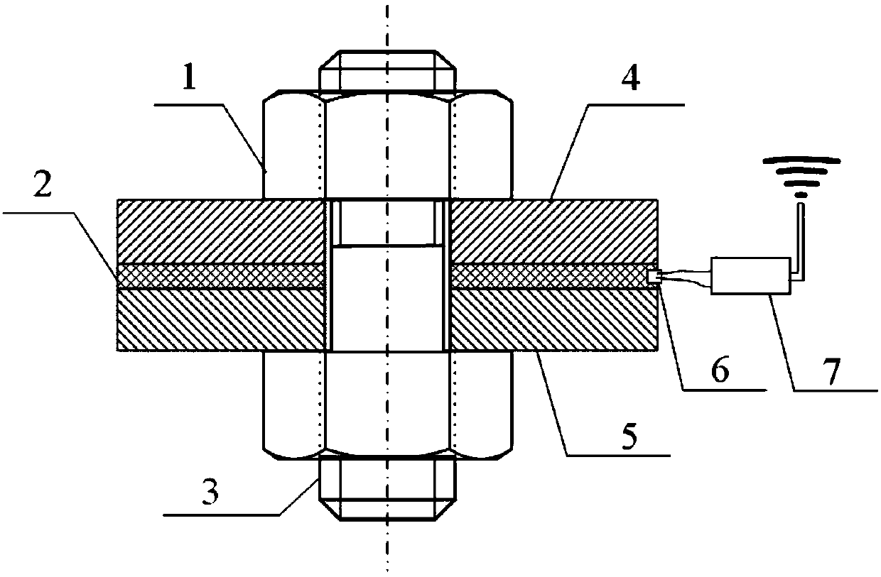
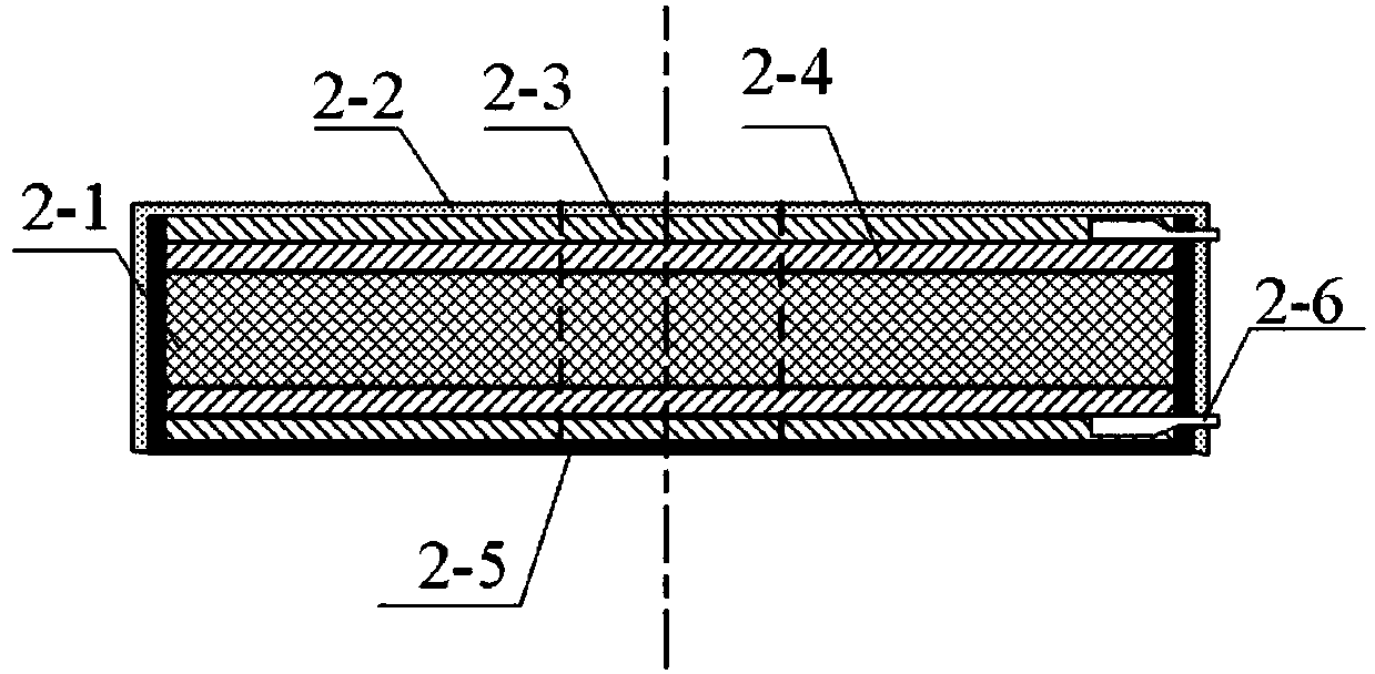
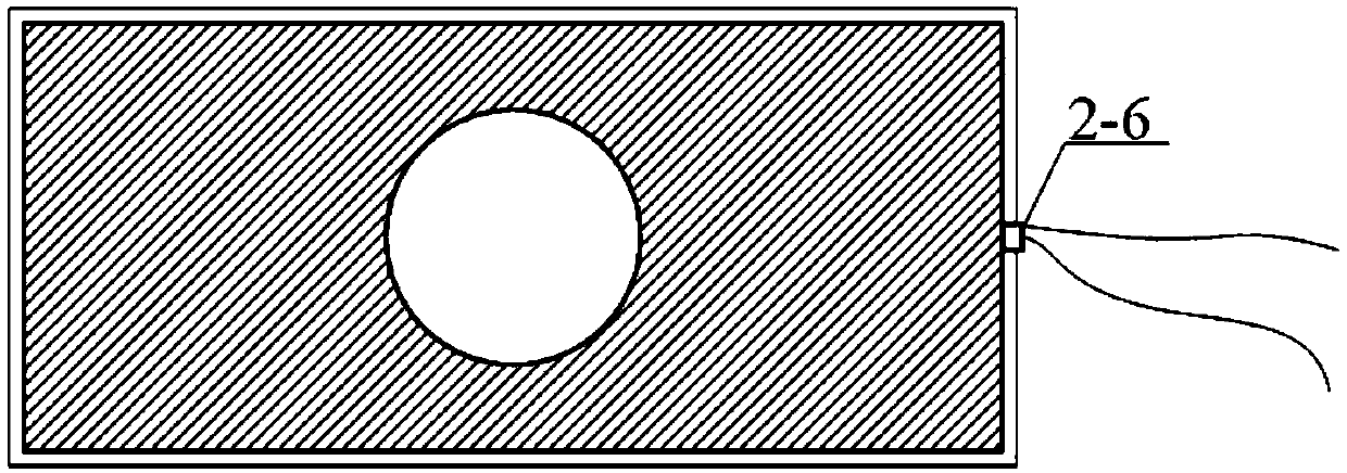
[0017] combine Figure 1-3 , the present invention is a bolt joint surface dynamic stress monitoring device, including a monitored structure body, a PVDF piezoelectric stress monitoring sensor 2 and a signal acquisition and processing circuit 3 . Among them, the PVDF piezoelectric stress monitoring sensor 2 is placed on the bolt joint surface of the two workpieces 4 and 5 to be monitored, and the concave protective shells 2-2 and 2-5 of the PVDF piezoelectric stress monitoring sensor 2 are provided with lead through holes 6 , the wire is connected to the signal acquisition and processing circuit 7 through the lead through hole 6, and the signal acquisition circuit 7 realizes the amplification, filtering and wireless transmission of the dynamic stress signal.

[0018] The monitored structural body includes a nut 1, a double-ended stud 3, an upper workpiece 4 and a...


PUM

PropertyMeasurementUnit
thicknessaaaaaaaaaa

Abstract

The invention aims to provide a bolt combination surface dynamic stress monitoring device. The bolt combination surface dynamic stress monitoring device is characterized in that a PVDF piezoelectric type stress monitoring sensor is placed at the combination surface of two monitored workpiece bolts, a shell of the PVDF piezoelectric type stress monitoring sensor is provided with a lead through hole, a wire is connected with a signal acquisition processing circuit through the lead through hole, the signal acquisition circuit is used for amplifying, filtering and wirelessly transmitting a dynamicstress signal, through holes used in cooperation with a double-head stud are formed in an upper workpiece and a lower workpiece, the PVDF piezoelectric type stress monitoring sensor comprises a concave protection shell, an insulation pressing connection layer, a conductive layer, a PVDF piezoelectric film and a wiring terminal, the signal acquisition processing circuit comprises a charge amplification circuit, a voltage amplification circuit, a filter circuit and a wireless signal transmission circuit. According to the bolt combination surface dynamic stress monitoring device, the structure is simple, the size is small, the operation is convenient, bolt combination surface dynamic stress implementation monitoring can be achieved, through the wireless transmission, the use space can be saved, and the wiring trouble can be reduced.

Description

technical field [0001] The invention relates to a stress monitoring device, in particular to a dynamic stress monitoring device for a bolt joint surface. Background technique [0002] In the fields of marine engineering, road and bridge pipelines, petrochemical industry, mechanical equipment and other fields, various parts are usually connected by bolts, welding and riveting, and most structures and equipment are connected by bolts. There is a contact surface between the connected parts, and the stress distribution of the bolted contact surface has an important impact on the service life of the bolt, the structural seal, and the stability of the mechanical system. The force on the contact surface of the bolt connection is relatively complicated. It not only has to bear alternating loads and temperature changes, but also transmits the unbalanced force generated by the operation of mechanical equipment. The weakest link of many mechanical systems mainly comes from the contact ...

Claims


Application Information

Patent Timeline
Patent Type & Authority Applications(China)
IPC IPC(8): G01L1/18
CPCG01L1/18
Inventor 杜敬涛陈琪赵雨皓
Owner HARBIN ENG UNIV
Why Eureka
Try Eureka