Particle focusing glare point speed measuring method based on correlation matching

A technology of correlation matching and particle imaging, which is applied in measuring devices, fluid velocity measurement, individual particle analysis, etc., can solve the difficulties of positioning and identification, and does not propose the IPI focusing two-point image tracking and matching method, so as to avoid errors and be accurate The effect of matching recognition rate

Active Publication Date: 2019-04-16
TIANJIN UNIV
View PDF7 Cites 8 Cited by
  • Summary
  • Abstract
  • Description
  • Claims
  • Application Information

AI Technical Summary

Problems solved by technology

Compared with the IPI circular fringe image, the focused two-point image is especially suitable for the measurement of high-density particle fields due to the reduced overlap, but its positioning and identification are more difficult, especially for high-density particle fields
At present, there is no proposed tracking and matching method suitable for IPI focusing on two-point images

Method used


Image

  • Particle focusing glare point speed measuring method based on correlation matching
  • Particle focusing glare point speed measuring method based on correlation matching
  • Particle focusing glare point speed measuring method based on correlation matching

Examples


Embodiment 1

[0030] The embodiment of the present invention provides a speed measurement experiment result based on the IPI focused image. The laser used in the experiment is a Nd:YAG double pulse laser with a wavelength of λ=532nm, the pulse emission time interval Δt=0.8ms, and the maximum pulse laser energy is 120mJ. The thin beam emitted by the laser passes through the beam expander and collimation system, and then is compressed into a sheet-like beam with a beam width of 0.9 mm by two cylindrical mirrors, and is divided into two beams of equal intensity by a beam splitter to irradiate the particle field. A focused image of the particle field is recorded at a scattering angle of 90°.

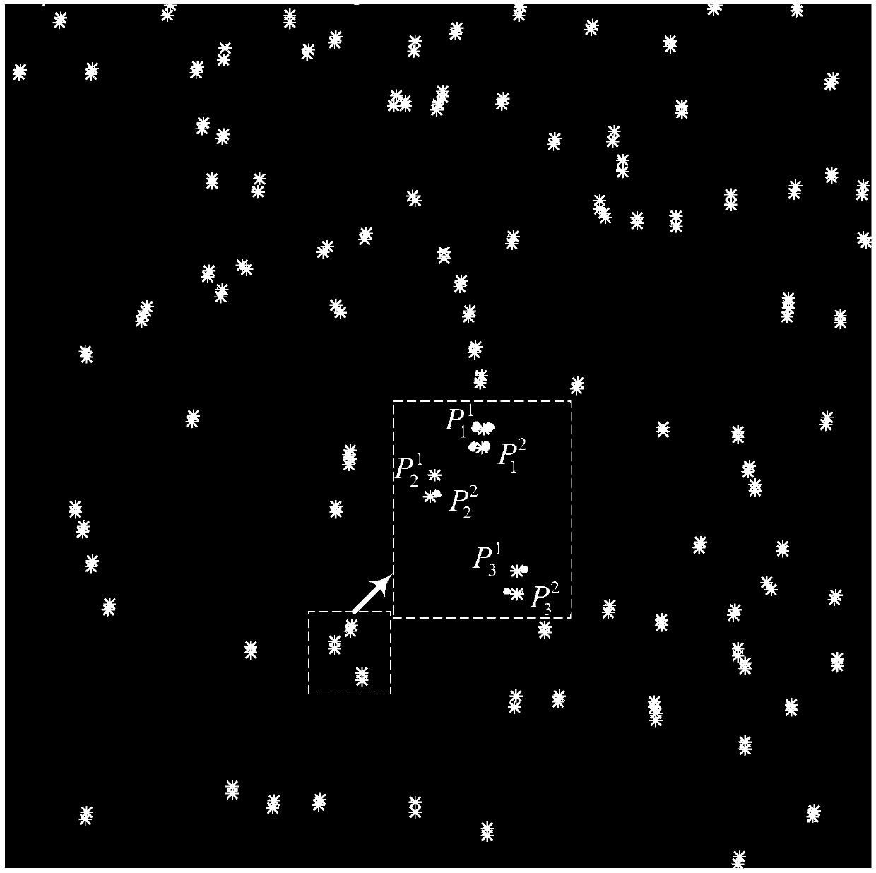
[0031] figure 2 The fuel temperature is 80°C, and the ambient back pressure is 1.0 bar, and the double-exposure and focused two-point images of the n-heptane spray field are collected. Correlate the focused two-point image with the sequence template, and then combine the centroid method to extract the p...

example 2

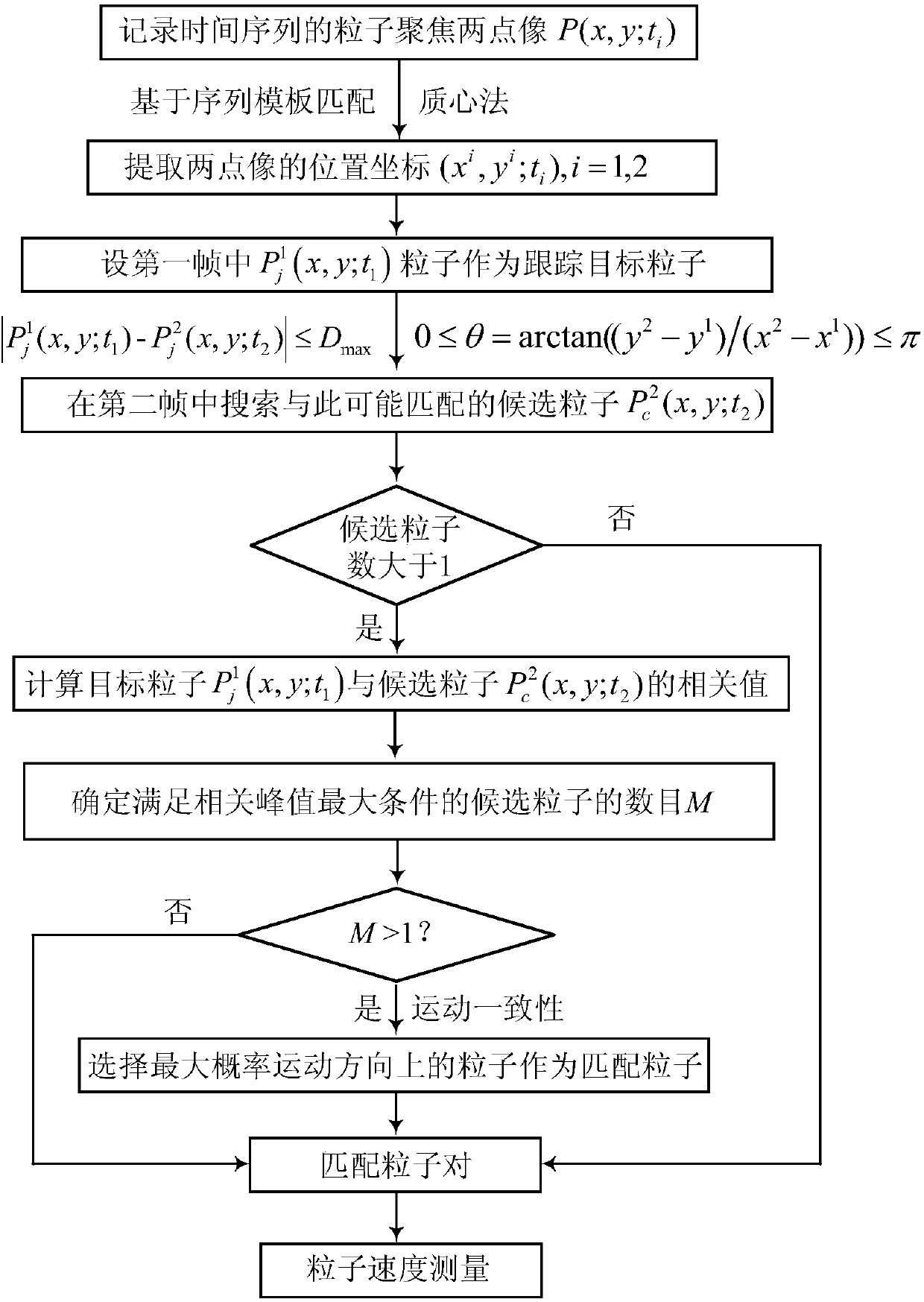
[0035] Example 2 gives the simulation analysis results. In the image square field of view of 512×512pixels, simulate two-point images of different numbers of randomly distributed particles, the distance between the two-point images is distributed between 4 and 20pixels, the particle movement displacement is from 0 to 20pixels, and the movement direction is from -90° to 0°. In order to reduce the randomness in the simulation, the average result of 50 simulations is taken as the final result. For each simulated two-point image of a particle, correlation calculations are performed based on the sequence template, combined with the centroid method, the position coordinates of the two-point image of each particle are extracted, and each particle is regarded as the target particle, according to the maximum displacement D max and velocity direction criteria to search for possible matching candidate particles. Based on the cross-correlation algorithm, the correlation value between th...


PUM

PropertyMeasurementUnit
diameteraaaaaaaaaa
diameteraaaaaaaaaa
diameteraaaaaaaaaa

Abstract

The invention discloses a particle focusing glare point speed measuring method based on correlation matching. The method is characterized in that a particle IPI focusing glare point of the time sequence is recorded, on the basis of a centroid method and a sequence template matching method, particle positioning of sub-pixels is realized, candidate particles are searched according to a maximum displacement and speed direction criterion, then on the basis of a cross correlation method, particle recognition matching with the high accurate recognition rate is achieved, the effect is that the methodis provided for the particle speed measurement based on the IPI focusing point, moreover, quite high speed measurement precision and quite high matching accuracy are achieved, and the method can be used for speed distribution measurement of the of particle fields such as sprayed mist, bubbles and flow fields.

Description

technical field [0001] The invention relates to the field of particle parameter measurement, in particular to an IPI (Interferometric Particle Imaging) particle focusing two-point image tracking and matching velocity measurement algorithm, and in particular to the improvement of the positioning accuracy of the particle two-point image and its matching accuracy. Background technique [0002] Particle velocity is an important parameter to characterize particle characteristics, and it is of great significance to study particle velocity measurement methods in spray fields and flow fields. The commonly used optical methods for particle velocimetry include laser Doppler velocimetry (LDV), phase Doppler velocimetry (PDA), particle image velocimetry (PIV) and particle tracking velocimetry (PTV). LDV and PDA are single-point velocity measurement technologies, which cannot provide instantaneous flow velocity data for the entire field. PIV and PTV technologies break through the limita...

Claims


Application Information

Patent Timeline
Patent Type & Authority Applications(China)
IPC IPC(8): G01P5/22G01N15/00G01N15/10
CPCG01N15/00G01N15/10G01N2015/0003G01N2015/1075G01P5/22
Inventor 吕且妮尉小雪付春帅
Owner TIANJIN UNIV
Why Eureka
Try Eureka