Loop antenna applied to wireless charging of implantable cardiac pacemaker

A technology for cardiac pacemakers and loop antennas, applied in loop antennas, individually powered antenna arrays, antennas, etc., can solve problems such as low transmission efficiency and short transmission distance, achieve the effect of reducing the antenna area and improving energy transmission efficiency

Pending Publication Date: 2019-04-16
XIAN JIAOTONG LIVERPOOL UNIV
View PDF0 Cites 2 Cited by
  • Summary
  • Abstract
  • Description
  • Claims
  • Application Information

AI Technical Summary

Problems solved by technology

These technologies have their own advantages and disadvantages, the main problems are short transmission distance and low transmission efficiency

Method used


Image

  • Loop antenna applied to wireless charging of implantable cardiac pacemaker
  • Loop antenna applied to wireless charging of implantable cardiac pacemaker
  • Loop antenna applied to wireless charging of implantable cardiac pacemaker

Examples


Embodiment

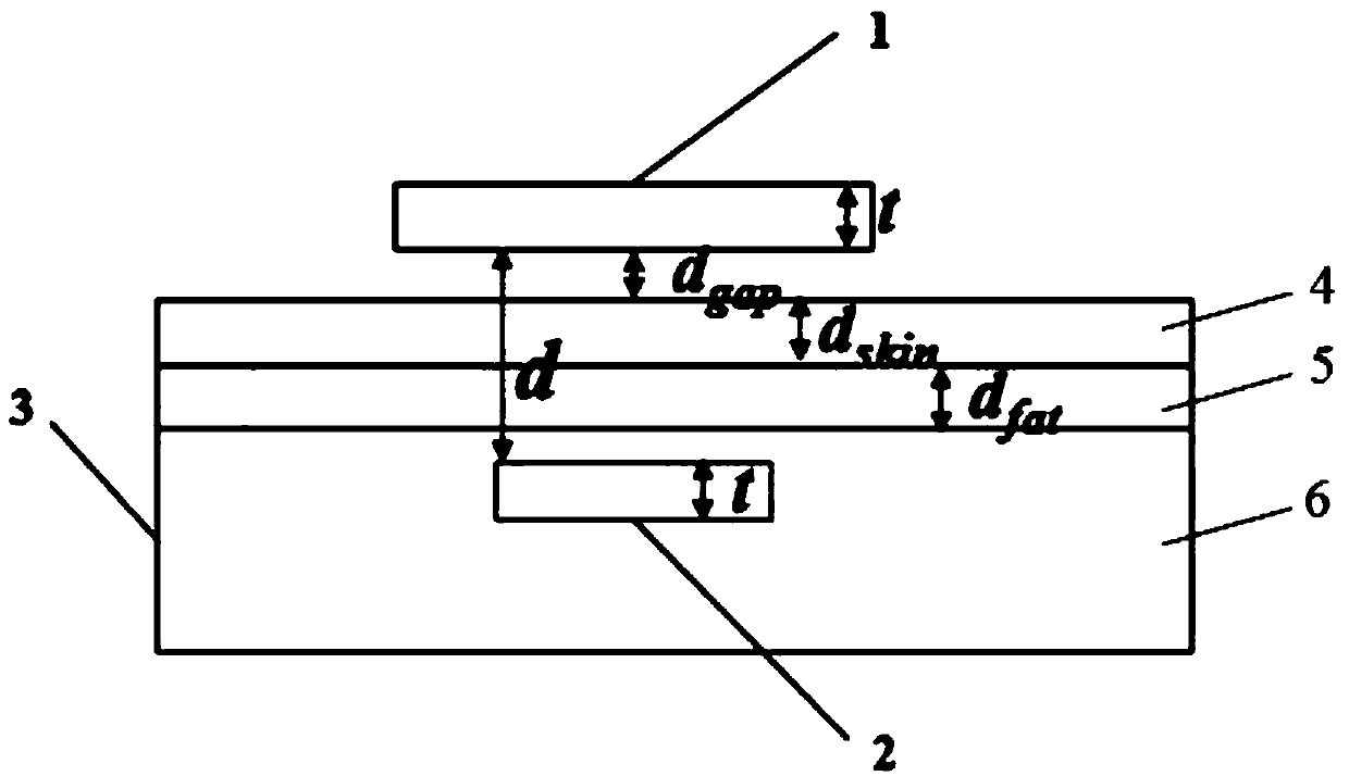
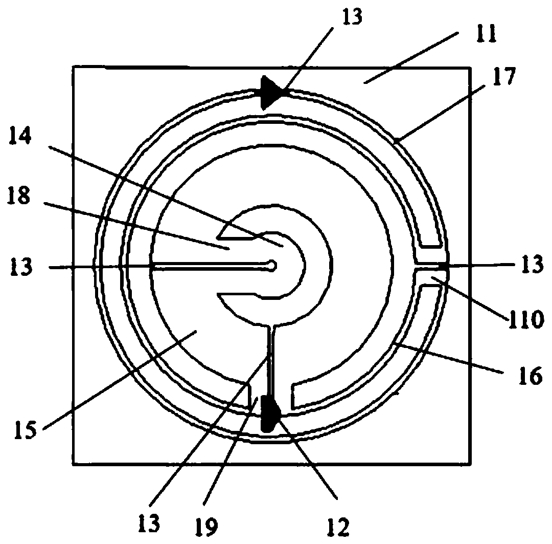
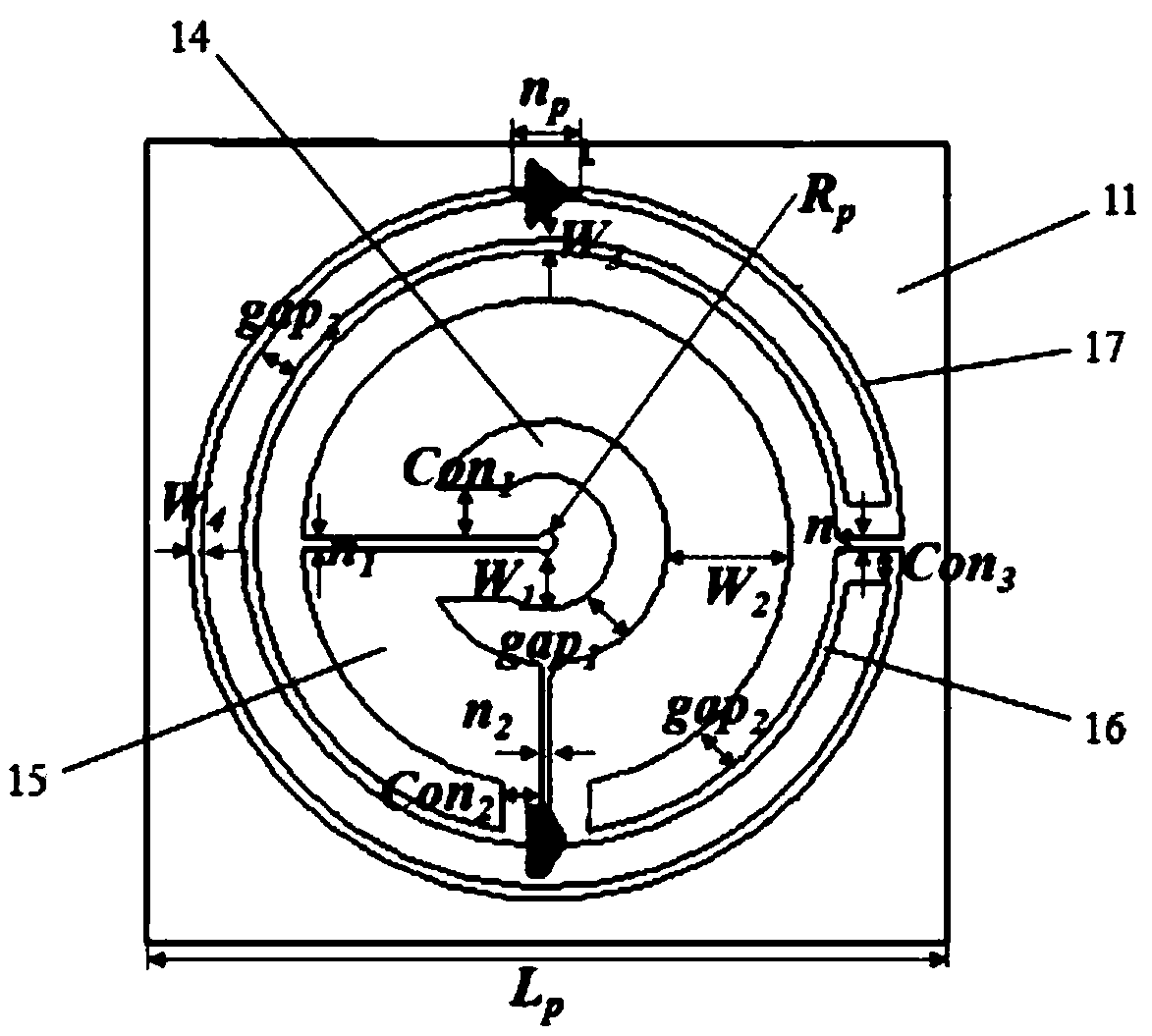
[0028] like Figure 1-4 As shown, a loop antenna applied to wireless charging of an implantable cardiac pacemaker includes an in vitro planar loop antenna 1 and an in vivo planar loop antenna 2; the in vivo planar loop antenna 2 is arranged in the body; the in vitro planar loop antenna 1 is arranged on the external skin; the external planar loop antenna 1 includes an external antenna substrate 11, an external circular radiation patch, a pair of connecting radiation patches and patch capacitors 12; the external external circular radiation patch is arranged on the external antenna On the substrate 11; the annular radiation patch is provided with at least one in vitro radiation patch gap 13; the chip capacitor 12 is arranged at the in vitro radiation patch gap 13; the in vitro annular radiation patch includes a first annular radiation patch sheet 14, the second annular radiation patch 15, the third annular radiation patch 16 and the fourth annular radiation patch 17; the paired c...


PUM


Abstract

The invention discloses a loop antenna applied to the wireless charging of an implantable cardiac pacemaker. The loop antenna comprises an in-vitro planar loop antenna and an in-vivo planar loop antenna. The in-vivo planar loop antenna is arranged in a body. The in-vitro planar loop antenna is arranged on the in-vitro skin. The in-vitro planar loop antenna comprises an in-vitro antenna substrate,an in-vitro loop radiation patch, paired connection radiation patches and a chip capacitor. The in-vitro loop radiation patch is arranged on the in-vitro antenna substrate. The loop radiation patch isprovided with at least one in-vitro radiation patch notch. The chip capacitor is arranged at the in-vitro radiation patch notch. The in-vitro loop radiation patch and the paired connection radiationpatches form a complete loop. The in-vitro loop radiation patch, the paired connection radiation patches and the chip capacitor are all arranged on the same surface of the in-vitro antenna substrate.According to the invention, the planar loop multi-loop wireless transmission antenna is adopted, so that the area of the antenna is reduced. The chip capacitor is introduced, so that the energy transmission efficiency is improved.

Description

technical field [0001] The invention relates to an antenna for wireless charging, in particular to a loop antenna for wireless charging of implantable cardiac pacemakers. Background technique [0002] In October 1958, Karolinska Hospital in Sweden completed the implantation of the world's first implantable artificial cardiac pacemaker. The operation was performed by the surgeon Professor Ake Senming. Designed by Dr. Rune Elmqvist of Schnander Company, the pacemaker has a circular shape and is powered by two nickel-cadmium batteries connected in series. It is charged through in vitro induction and needs to be charged once a week. Patient Arne Larsson suffered from complete atrioventricular block and frequently suffered from A-Syndrome caused by cardiac arrest, and the effect of drug treatment was not good. The patient lived and worked with a pacemaker for 46 years from the age of 40, and died of cancer at the age of 86. A total of 26 pacemakers were replaced in his life. ...

Claims


Application Information

Patent Timeline
Patent Type & Authority Applications(China)
IPC IPC(8): H01Q1/38H01Q7/00H01Q21/00H02J50/27A61N1/375A61N1/378
CPCA61N1/37512A61N1/378H01Q1/38H01Q7/00H01Q21/00H02J50/27A61N1/3787A61N1/37229H02J2310/23H01Q21/06
Inventor 林永义王璟琛王炤马波力黄漪
Owner XIAN JIAOTONG LIVERPOOL UNIV
Why Eureka
Try Eureka