Power conversion device

A power conversion device and power technology, applied in the direction of converting irreversible AC power input into DC power output, etc., to achieve the effects of high harmonic countermeasures, miniaturization and simple structure

Active Publication Date: 2019-04-16
MITSUBISHI ELECTRIC CORP
View PDF9 Cites 0 Cited by
  • Summary
  • Abstract
  • Description
  • Claims
  • Application Information

AI Technical Summary

Problems solved by technology

Therefore, electrical equipment connected to each system sets limits on the amount of harmonic generation

Method used


Image

  • Power conversion device
  • Power conversion device

Examples


Embodiment approach 1

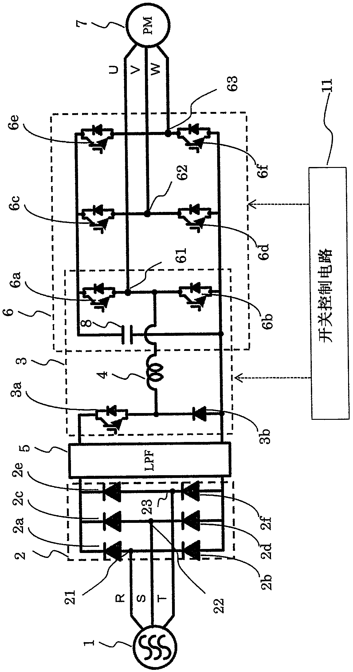
[0020] figure 1 It is a configuration diagram showing the configuration of the power conversion device according to Embodiment 1 of the present invention. Such as figure 1 As shown, the power conversion device has a three-phase diode rectifier 2 , a buck-boost converter 3 , a low-pass filter (LPF: Low-Pass Filter) 5 , and a three-phase voltage-type inverter 6 .

[0021] Such as figure 1 As shown, the power conversion device is connected to the system power supply 1 . The system power supply 1 is composed of a commercial power supply, that is, a three-phase AC power supply. The power converter converts the commercial three-phase AC power from the system power supply 1 into the three-phase AC power required by the motor 7 to drive the motor 7 . Here, a description will be given assuming that the drive target of the power conversion device is the electric motor 7 .

[0022] A three-phase diode rectifier 2 is connected to the system power supply 1 . The three-phase diode rec...


PUM


Abstract

The power conversion device is provided with: a diode rectifier (2); a step up / down converter (3) that performs alternating current-direct current conversion; and an inverter (6) that supplies a drivecurrent to an electric motor (7) from series connection points (61-63) of first to third arms. The step up / down converter (3) is configured from: a converter switching element (3a) connected to the positive electrode side of the diode rectifier (2); a converter passive element (3b), in which the anode is connected to the negative electrode side of each of the arms of the inverter (6), and to thenegative electrode side of the diode rectifier (2), and the cathode is connected to the converter switching element (3a); the first arm of the inverter (6); and a direct current reactor (4) that is connected between the series connection point (61) of the first arm, and the cathode of the converter passive element (3b). The first arm of the inverter (6) is shared with the step up / down converter (3).

Description

technical field [0001] The present invention relates to a power conversion device, in particular to a power conversion device with a high-order harmonic suppression function. Background technique [0002] In recent years, with the popularization of electrical equipment, the amount of harmonic current has increased, and the quality degradation of the power system has become a problem. Therefore, electrical equipment connected to each system sets limits on the amount of harmonic generation. Accepting this reality, methods for countermeasures against harmonics using reactors, active components, and the like have been proposed in various electrical equipment. [0003] As conventional harmonic countermeasures on the power system side, there are mainly the following two methods. [0004] The first method is a method of providing a reactor for three-phase AC on the power supply side (for example, refer to Patent Document 1, for example). [0005] The second method is a method in...

Claims


Application Information

Patent Timeline
IPC IPC(8): H02M7/12
CPCH02M7/12H02M1/4225
Inventor 松井光生
Owner MITSUBISHI ELECTRIC CORP
Why Eureka
Try Eureka