Knife rest for multi-wire cutting machine and multi-wire cutting machine with same

A multi-wire cutting machine and tool holder technology, which is applied to fine working devices, working accessories, stone processing equipment, etc. Wire spindle steel wire, reducing the cutting accuracy of thicker materials, etc.

Pending Publication Date: 2019-04-19
玉田县昌通电子有限公司
View PDF0 Cites 6 Cited by
  • Summary
  • Abstract
  • Description
  • Claims
  • Application Information

AI Technical Summary

Problems solved by technology

Multi-wire cutting machine in the prior art (as figure 1 , figure 2 As shown), the knife holder is integrated, because the two lower winding spindles and the upper winding spindle have the same wire groove, during the process of cutting thicker materials, the wire spacing of the lower layer steel wire is larger, and the steel wire is easy to contact with the wire. Scuffing occurs between the groove wall of the lower winding spindle and the groove wall of the upper w...

Method used


Image

  • Knife rest for multi-wire cutting machine and multi-wire cutting machine with same
  • Knife rest for multi-wire cutting machine and multi-wire cutting machine with same
  • Knife rest for multi-wire cutting machine and multi-wire cutting machine with same

Examples


Embodiment Construction

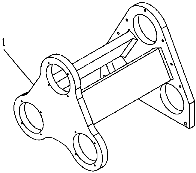
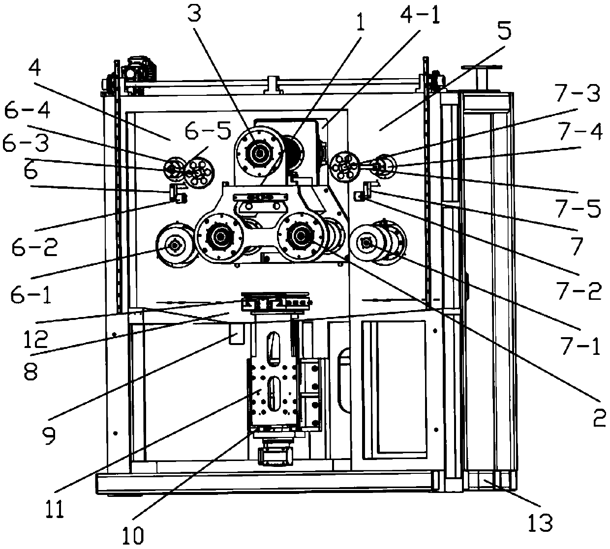
[0431] Such as Figure 5 to Figure 7 As shown, this embodiment provides a knife rest for multi-wire cutting machine, the knife rest 1 is divided into a knife rest lower body 1-1 and a knife rest upper body 1-2, the knife rest lower body 1-1 and the The tool holder upper body 1-2 is connected in rotation through the shaft body assembly 1-3.

[0432] This embodiment adopts the technical means that the tool rest is divided into a lower body and an upper body of the tool rest, and the lower body of the knife rest and the upper body of the knife rest are connected by a shaft assembly through a technical means, so it can be aimed at For different thickness slicing requirements, especially large thickness slicing requirements, adjust the spacing of steel wires, and at the same time, if Figure 30 As shown, the upper body of the tool holder can be rotated and adjusted according to the direction of the upper steel wire, so that the direction of the groove of the upper winding spindle ...


PUM


Abstract

The invention discloses a knife rest for a multi-wire cutting machine and the multi-wire cutting machine with the same. The knife rest is divided into a knife rest lower body and a knife rest upper body, the knife rest lower body and the knife rest upper body are rotationally connected through a shaft assembly, the shaft body assembly includes a shaft body and a shaft seat assembly, the shaft bodyis rotationally connected with the shaft seat assembly, the shaft body sequentially comprises a lower shaft body, an upper shaft body, a top fixing disc and a pulling head which are coaxial from bottom to top, and the shaft seat assembly comprises a bearing seat, a bearing, an oil seal cover, an oil seal and an end cover. The multi-wire cutting machine includes the above knife rest. According tothe requirement for slicing sheets with different thicknesses, in particular to the requirement for slicing sheets with large thicknesses, the spacing between steel wires is adjusted, the adjusted steel wires are reliably wound in wire troughs, scraping with wire trough walls is not prone to happening, moving to other wire troughs is not prone to happening, accurate cutting is achieved, the cutting precision and efficiency are greatly improved, and the service life of an upper winding main shaft, a lower winding main shaft and the steel wires is prolonged.

Description

technical field [0001] The invention relates to a multi-wire cutting device, in particular to a tool holder for a multi-wire cutting machine and the multi-wire cutting machine. Background technique [0002] Multi-wire cutting is a method of grinding and cutting the hard and brittle materials sent into the processing area into hundreds or even thousands of thin slices through high-speed reciprocating movement of steel wires. Multi-wire cutting machine in the prior art (as figure 1 , figure 2 As shown), the knife holder is integrated, because the two lower winding spindles and the upper winding spindle have the same wire groove, during the process of cutting thicker materials, the wire spacing of the lower layer steel wire is larger, and the steel wire is easy to contact with the wire. Scuffing occurs between the groove wall of the lower winding spindle and the groove wall of the upper winding spindle. In severe cases, wire jumping problems will occur. This will not only ea...

Claims


Application Information

Patent Timeline
IPC IPC(8): B28D5/04B28D7/02B28D7/00
CPCB28D5/045B28D5/0058B28D5/0076
Inventor 章博
Owner 玉田县昌通电子有限公司
Why Eureka
Try Eureka