Factory prefabricated outdoor electrical equipment base, and manufacturing method and mounting method thereof

A technology of factory prefabrication and power equipment, applied in infrastructure engineering, manufacturing tools, ceramic molding machines, etc., can solve the problems of construction efficiency, difficult control of construction quality, low turnover rate and industrialization degree, and high construction complexity. The quality is easy to control, the turnover rate and the degree of industrialization are high, and the effect of reducing construction waste and dust pollution

Pending Publication Date: 2019-04-19
西安西微电力设备有限公司
View PDF0 Cites 2 Cited by
  • Summary
  • Abstract
  • Description
  • Claims
  • Application Information

AI Technical Summary

Problems solved by technology

[0003] The purpose of the present invention is to provide a factory prefabricated outdoor power equipment foundation and its manufacturing method and installation method, to solve the problems of on-site pouring and masonry in the construction of power equipment foundations existing in the existing "wet method" construction technology, which is affected by seasons, climate, personnel, etc. Factors are greatly affected, the excavation volume is large, the construction complexity is high, and the construction efficiency and construction quality are not easy to control, the turnover rate and the degree of industrialization are low, the average cost is high, and the impact on the surrounding environment is large.

Method used


Image

  • Factory prefabricated outdoor electrical equipment base, and manufacturing method and mounting method thereof
  • Factory prefabricated outdoor electrical equipment base, and manufacturing method and mounting method thereof
  • Factory prefabricated outdoor electrical equipment base, and manufacturing method and mounting method thereof

Examples


Embodiment 1

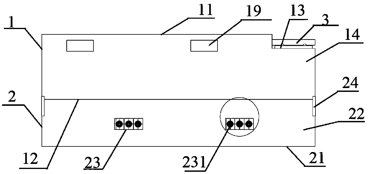
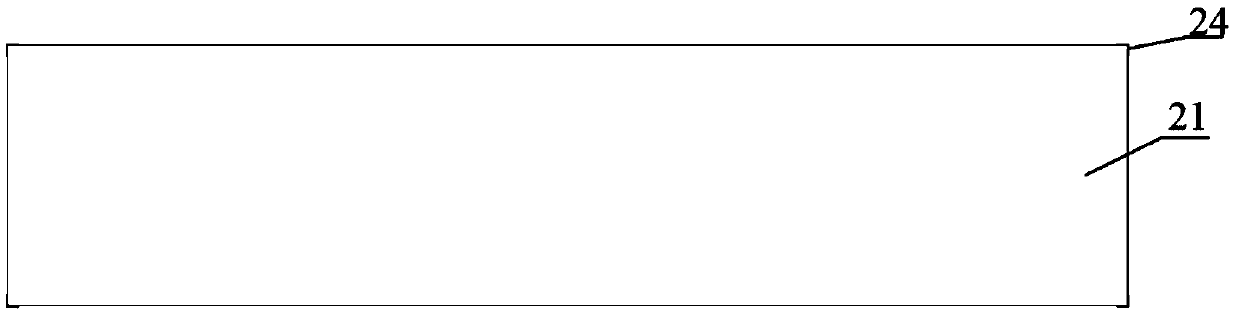
[0044] The factory prefabricated outdoor power equipment foundation described in this embodiment, see Figure 1-7 , including an upper foundation 1, a lower foundation 2 and a manhole cover 3, the lower foundation 2 is connected with the upper foundation 1, the upper foundation 1 is provided with a foundation upper opening 11, a foundation lower opening 12 and a lower wellhead 13, the lower foundation The wellhead 13 is provided with a well cover 3; the lower foundation 2 is an integrally formed rectangular box structure composed of a lower bottom plate 21 and a lower foundation side plate 22; Formed rectangular frame construction. The side wall of the lower foundation 2 is provided with several cable holes 23; the cable hole 23 is provided with a cable sealing device 231, see Figure 8 And Fig. 9; the upper part of the side wall of the upper foundation 1 is provided with several ventilation openings 19, and the ventilation openings 19 are provided with mesh covers. The uppe...

Embodiment 2

[0046] The manufacturing method of the factory prefabricated outdoor power equipment foundation described in Embodiment 1 includes the following steps:

[0047] (1) Design the reinforcement drawings of the upper foundation 1, the lower foundation 2 and the manhole cover 3 according to the outline and structural dimensions of the drawings of the factory prefabricated outdoor power equipment foundation;

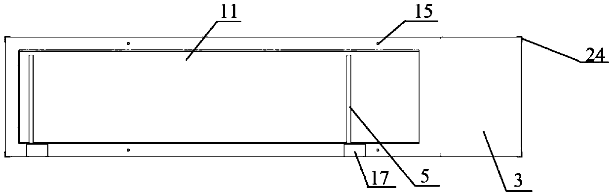
[0048] (2) According to the reinforcement diagram of upper foundation 1, lower foundation 2 and manhole cover 3 described in step (1), bend and bind the reinforcement skeleton, at the position required by the drawing in step (1), place the reinforcement on upper foundation 1 and lower foundation 2 Fix the hoisting embedded part 15, install the embedded part 16, the first metal conductor 17, the second metal conductor 18, and the guide part 24 in the skeleton, connect the first metal conductor 17 and the steel bar inside the upper foundation 1 by welding, and connect all the The...

Embodiment 3

[0055] The installation method of the factory prefabricated outdoor power equipment foundation described in Embodiment 1 includes the following steps:

[0056] (1) The lower foundation 2 is fully buried underground, pouring mortar on the upper surface of the lower foundation 2, and then the upper foundation 1 is installed on the upper surface of the lower foundation 2 through the guide 24 on the lower foundation 2;

[0057] (2) The air vent 19 on the upper part of the side wall of the upper foundation 1 is exposed to the ground, and the wellhead 13 of the lowering is higher than the ground, and the cable support 4 is fixed by screwing on the inner surface of the upper foundation side plate 14 by installing the embedded part 16 Connecting, connecting the ground bus bar 5 to the first metal conductor 17, the second metal conductor 18, and the cable support 4, and the lower end of the ground bus bar 5 extends to the lower base plate 21 of the lower foundation 2;

[0058] (3) A ca...


PUM


Abstract

The invention belongs to the technical field of outdoor electrical equipment bases, and particularly relates to a factory prefabricated outdoor electrical equipment base, and a manufacturing method and a mounting method thereof. The factory prefabricated outdoor electrical equipment base comprises an upper base, a lower base and a well cover; the lower base is connected with the upper base; the upper base is provided with an upper base opening, a lower base opening and a man well head; the well cover is arranged on the man well head; the lower base is of a rectangular box body structure whichis integrally formed by a lower bottom plate and lower base side plates; the upper base is of a rectangular frame structure which is integrally formed by enclosing upper base side plates; a pluralityof cable holes are formed in the side walls of the lower base; cable sealing devices are arranged in the cable holes; and a plurality of ventilation openings are formed in the upper parts of the sidewalls of the upper base. The factory prefabricated outdoor electrical equipment base is a factory reinforced concrete prefabricated piece and is not affected by the factors, such as season, climate and personnel; and the excavated volume of earthwork is low. Moreover, the construction efficiency and the construction quality are both easy to control; and both the turnover rate and the industrialization degree are high.

Description

technical field [0001] The invention belongs to the field of outdoor power equipment foundation technology, and in particular relates to a factory prefabricated outdoor power equipment foundation and a manufacturing method and an installation method thereof. Background technique [0002] With outdoor power equipment such as ring network cabinets, switching stations, box transformers, etc. widely used in urban infrastructure. In recent years, it has become a rapid growth trend, but these power equipment need to be installed on a hollow foundation at the bottom of a cement structure, and the cables pass through the ring main unit from the inside of the foundation. At present, the foundation construction still adopts traditional cast-in-place concrete and masonry methods. Because it adopts the "wet method" construction, that is, on-site pouring and masonry, which is greatly affected by factors such as seasons, climate, and personnel, the excavation volume of earthwork is large...

Claims


Application Information

Patent Timeline
Patent Type & Authority Applications(China)
IPC IPC(8): E02D27/01E02D27/44B28B23/02B28B1/14
CPCE02D27/016B28B1/14B28B23/02E02D27/44
Inventor 李兆利
Owner 西安西微电力设备有限公司
Why Eureka
Try Eureka