Novel high-temperature superconducting cable with built-in optical fiber and manufacturing method thereof

A high-temperature superconducting technology with built-in optical fibers, applied in the field of power transmission technology, can solve problems such as difficult installation, complicated wiring, and influence of superconducting cable structure, and achieve the effect of ensuring safe operation

Pending Publication Date: 2019-04-19
SHENZHEN POWER SUPPLY BUREAU
View PDF0 Cites 14 Cited by
  • Summary
  • Abstract
  • Description
  • Claims
  • Application Information

AI Technical Summary

Problems solved by technology

[0004] The existing temperature measurement methods such as thermocouples, thermal resistance and other traditional temperature sensors cannot be used due to their difficult installation and complicated wiring, which will have a great impact on the structure of superconducting cables, and their temperature measurement accuracy is susceptible to electromagnetic interference. Temperature monitoring along the cable
At present, there have been studies on the application of optical fiber temperature measurement to the temperature measurement along the cable, but the research is still in the stage of installing the optical fiber on the outer wall of the cable skeleton, the cable insulation layer or the shielding layer, and due to the low thermal conductivity of the insulation layer, the superconducting cable The temperature change on the phase conductor cannot be sensed by the optical fiber through the insulating layer, and it is still impossible to effectively measure the temperature along the conductor on the cable

Method used


Image

  • Novel high-temperature superconducting cable with built-in optical fiber and manufacturing method thereof
  • Novel high-temperature superconducting cable with built-in optical fiber and manufacturing method thereof
  • Novel high-temperature superconducting cable with built-in optical fiber and manufacturing method thereof

Examples


Embodiment Construction

[0034] The following will clearly and completely describe the technical solutions in the embodiments of the present invention with reference to the accompanying drawings in the embodiments of the present invention. Obviously, the described embodiments are only part of the embodiments of the present invention, not all of them. Based on the embodiments of the present invention, all other embodiments obtained by persons of ordinary skill in the art without making creative efforts belong to the protection scope of the present invention.

[0035] The following will refer to the attached Figures 1 to 4 Examples of the present invention will be specifically described.

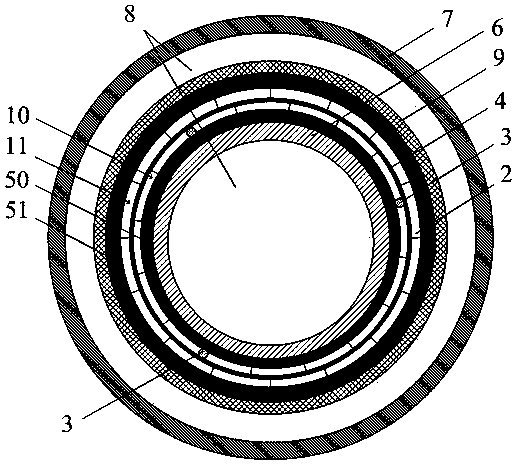
[0036] Such as figure 1 As shown, this embodiment provides a novel high-temperature superconducting cable with built-in optical fibers. In this embodiment, its structure includes:

[0037] In order to solve the above-mentioned technical problems, an aspect of the embodiments of the present invention provides a nove...


PUM

PropertyMeasurementUnit
widthaaaaaaaaaa
thicknessaaaaaaaaaa

Abstract

An embodiment of the invention provides a high-temperature superconducting cable with a built-in optical fiber. The high-temperature superconducting cable comprises a cryostat, a shielding layer, an outer insulating layer, at least one conductor layer, an inner insulating layer, and a cable framework from outside to inside, wherein liquid nitrogen fills between the cryostat and the shielding layerand fills in the cable framework; each conductor layer is formed by winding a plurality of high-temperature superconducting tape materials spirally; a carbon paper layer is laid between different conductor layers; and a temperature measuring optical fiber is at least laid in a gap between two adjacent high-temperature superconducting tape materials in one conductor layer. The invention further provides a corresponding manufacturing method. By implementing the novel high-temperature superconducting cable and the manufacturing method thereof, the temperature distribution along the cable conductor layers can be directly detected since the temperature measuring optical fiber is in direct contact with the superconducting cable conductor layers; meanwhile, the temperature measuring optical fiber is small in size and installed between the superconducting tape material gap, does not affect the cable body structure, does not affect the cable insulation performance, and is not subject to electromagnetic interference.

Description

technical field [0001] The invention relates to the application field of power transmission technology, in particular to a novel high-temperature superconducting cable capable of measuring the temperature of a conductor layer along the cable and a manufacturing method thereof. Background technique [0002] Compared with conventional power cables, high-temperature superconducting cables have the advantages of strong flow capacity, small loss, large capacity, compact structure, and no electromagnetic radiation pollution. At present, there are many high-temperature superconducting cables in operation worldwide. [0003] Different from the application of conventional power cables, the operating environment of high-temperature superconducting cables must be at least below the temperature of liquid nitrogen (-196°C). Therefore, when the temperature of the cable rises above the liquid nitrogen temperature due to local thermal disturbance or short-circuit current, it will have two e...

Claims


Application Information

Patent Timeline
Patent Type & Authority Applications(China)
IPC IPC(8): H01B12/00H01B12/02H01B12/16H01B13/00H01B13/06H01B13/22G01K11/32
CPCH01B12/00H01B12/02H01B12/16H01B13/00H01B13/06H01B13/22G01K11/32Y02E40/60
Inventor 庞骁刚胡子珩廖建平章彬汪桢子汪伟
Owner SHENZHEN POWER SUPPLY BUREAU
Why Eureka
Try Eureka