
Indoor positioning method based on reverse positioning principle

An indoor positioning and principle technology, applied in location information-based services, specific environment-based services, positioning, etc., can solve problems such as difficult clock synchronization, increased delay, and high cost

Inactive Publication Date: 2019-04-19
EAST CHINA NORMAL UNIV
View PDF6 Cites 6 Cited by
  • Summary
  • Abstract
  • Description
  • Claims
  • Application Information

AI Technical Summary

Problems solved by technology

[0006] The disadvantages of the above-mentioned prior art are: 1) This method requires strict clock synchronization between the transmitter and the receiver to ensure that the time of transmission and reception has the same clock reference, but in actual application scenarios, it is difficult to realize the synchronization between the user and the positioning base station. 2) If the clock synchronization conditions are not available, the distance between the user and the base station is generally obtained by measuring the time required for the round trip of the signal through two-way communication. The disadvantage of this is that the two-way communication causes an increase in delay. Make clock synchronization more difficult, and two-way communication makes transmitter and receiver equipment complex and costly

Method used


Image

  • Indoor positioning method based on reverse positioning principle
  • Indoor positioning method based on reverse positioning principle
  • Indoor positioning method based on reverse positioning principle

Examples


Embodiment

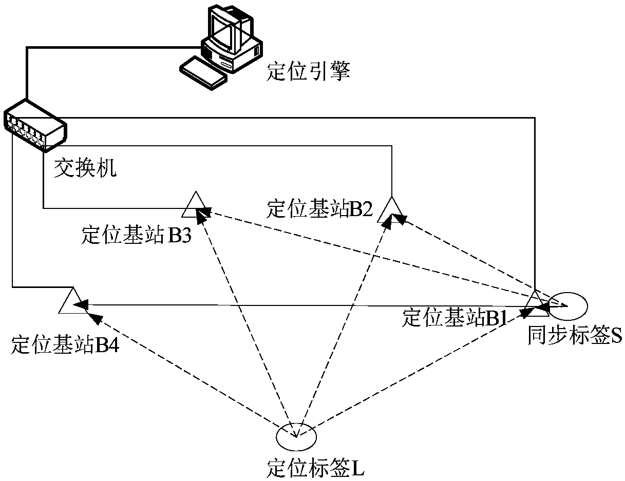
[0086] The invention discloses an indoor positioning method based on the principle of inverse positioning. figure 1 A specific example of the invention is given. This specific embodiment is made up of following several unit modules:

[0087] (1), a synchronization tag S;

[0088] (2), a positioning label L;

[0089] (3), four positioning base stations B1, B2, B3, B4;

[0090] (4), switch;

[0091] (5), positioning engine;

[0092] (6), cable.

[0093] Such as figure 1 As shown, this specific embodiment adopts a one-way transmission signal mode, that is, the synchronization tag and the positioning tag regularly transmit ultra-wideband narrow pulse wireless signals to the four positioning base stations. The positioning base station and the switch, and the switch and the positioning engine are all connected by cables. After the positioning base station receives the ultra-wideband narrow pulse wireless signal, it encapsulates the received synchronization packet and posit...


PUM


Abstract

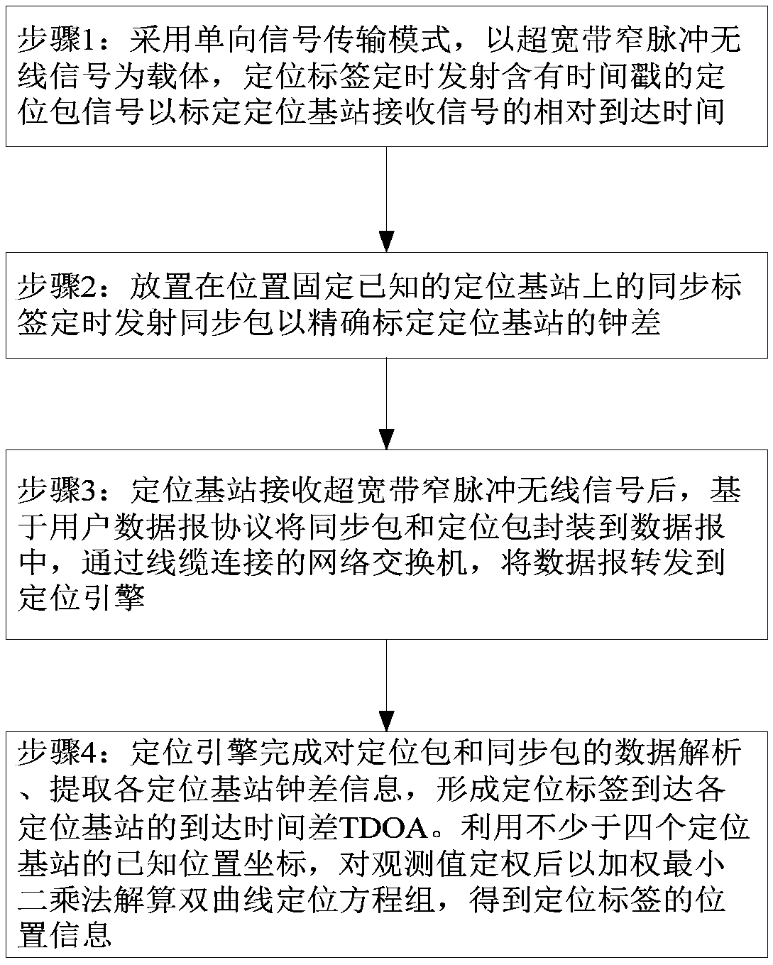
The invention discloses an indoor positioning method based on the reverse positioning principle. The method comprises the following steps: a one-way transmission signal mode is adopted, a positioningtag periodically transmits a positioning packet containing a timestamp to calibrate a relative arrival time of a received signal of a positioning base station; the positioning tag periodically transmits a synchronization packet to accurately calibrate a clock difference of the positioning base station; the positioning base station packages the received synchronization packet and the positioning packet into a datagram based on a user datagram protocol, and forwards the datagram to a positioning engine through a switch; the positioning engine completes the data analysis of the positioning packetand the synchronization packet, and forms an arrival time difference of the positioning tag to each positioning base station; after an observation value is weighted by using a known position of the positioning base station, a hyperbolic equation is solved by using a weighted least squares method to obtain a spatial location of the positioning tag. By adoption of the indoor positioning method disclosed by the invention, the clock difference of the positioning base station can be accurately measured, the indoor positioning accuracy is improved, the software and hardware costs of the positioningtag can also be reduced, and the scheme is simple and is easy to implement.

Description

technical field [0001] The invention relates to the technical field of positioning and location services based on wireless communication, and proposes an indoor positioning method based on the principle of inverse positioning. In this way, the clock error of the positioning base station is accurately calibrated by using the fixed and known synchronization tag to transmit the synchronization packet, which is conducive to improving the indoor positioning accuracy. Background technique [0002] Indoor positioning refers to the positioning of objects or people in an indoor environment. In recent years, industries such as industrial manufacturing, robotics, nursing homes, prisons, warehouses, shopping malls, and other industries have an increasing demand for indoor positioning. The difficulty is mainly reflected in the contradiction between improving the positioning accuracy and reducing the complexity and cost of the implementation scheme. [0003] A kind of indoor positioning...

Claims


Application Information

Patent Timeline
IPC IPC(8): H04W4/021H04W4/33H04W64/00G01S5/08
CPCG01S5/08H04W4/021H04W4/33H04W64/003
Inventor 余超郑正奇董大南
Owner EAST CHINA NORMAL UNIV
Learn More